

|
Click here for more Ham Radio Articles on this Site |
WA1LMV/R Repeater Tower
In 2026 I celebrated |


I am a licensed Amateur Radio Operator and repeater builder. I was first licensed as WN1LMV as a novice in 1969 at 16 years old. My dad, Henry, inspired my interest in electronics. He was a gread dad. He was a supervisor at a company that made movie projectors. He would bring home random surplus components and diagrams and generously shared his workshop and workspace with me. I would eventually build copies of their amplifiers at home. Later in life, he became a Ham and was licensed as WA1YHM.
My Ham Radio mentor was my high school science teacher, John Lindholm, W1XX. There, we started a Ham Radio Club with John as the faculty sponsor. John was the best science teacher, a great Ham Radio Mentor and a good friend. Because of him, several of my schoolmates also became licensed hams. Among those are Jay Rusgrove, W1VD of Advanced Receiver Research. I upgraded to the General Class license as WA1LMV while still in high school. I took the General Class exam in 1971 at the FCC office at Custom House in Boston. I took the Advanced Class exam in 1972 at the FCC field office in Hartford. In 2016 I applied for the vanity callsign W1RHS. Because I was not interested in Morse Code I did not upgrade to Extra Class license in my younger years. After retirement I finally decided to upgrade since the Morse Code test was no longer required. Of course, the FCC revised the exam questions in 2020. They became harder that the ones from past years. I passed the Extra Class exam with a grade of 98% just before my 70th birthday. Only about 21% of all hams have earned the Extra Class License. In August of 2024 I was granted the vanity callsign change to WR1S. Higher class licenses are allowed to have callsigns with fewer letters if the callsign you requested is available.
I am a retired IT professional having held technical and management positions with Eastman Kodak, Sun Microsystems and Oracle.
I am not a DXer, contester or a fan of CW (Morse Code). I am mainly a builder and experimenter. As a novice I built my first transmitter. It was a simple 15 watt CW transmitter on the 40 meter band using a single 6L6 tube as a Colpitts oscillator with a surplus FT-243 crystal from World War II. It was built on a Bud aluminum chassis with a transformer and filter capacitor from an old TV. I later modified the tank circuit to work as a trippler on the 15 meter band.
In the mid 1970s, I gravitated toward digital technologies starting with mechanical Teletype machines using them for Radio Teletype (RTTY). My first Teletype was a Model 15 [Model 15 You Tube Video] using a homemade vacuum tube terminal unit (modem) with a mercury wetted relay. Later I built a home-made ST-6 terminal unit and upgraded to Model 28 ASR and 35 ASR machines. I had the special service tools and service manuals and was pretty good at repairing all kinds of problems. [Model 35 You Tube Video] My Teletype experience led me to volunteering for a period of time at the American School for the Deaf. Back in the '70s and '80s, Teletypes were used with dial-up modems so that hearing impaired people could communicate from home using their regular phone lines. I conversed with other hams throughout the country typing to each other with the Teletype machines connected to our radios.
I have built and operated several VHF and UHF repeater systems throughout central Connecticut. In 1974 while still in college I was recruited into the technical committee of the Insurance City Repeater Club. There I was responsible for the vacuum tube to solid state upgrade of the WR1ABM repeater on 28/88 in Avon CT, the installation of the Avon UHF repeater, and the installation of the WR1AFU 75/15 repeater and 6 meter remote base in Burlington CT. One of our club members owned a two-way radio business. He was very generous, supporting the club with donations of equipment and loaning of service tools. My affiliation with him gained me service experience on a wide variety of commercial radio equipment from Motorola, GE and RCA and later with Kenwood NXDN as well as the ability to install my own repeater on the company's radio tower.
Along with John, W1GPO, and Jim, W1JJA (WA1IXU), I was one of the 6 Meter repeater pioneers in Connecticut with WR1AIB on 52.01 / 53.01 in Burlington in 1978. I designed and built an array of repeater controllers for the repeater club and my own repeater using discrete TTL logic. Later in the 1990s I designed and built the hardware and wrote the software for an 8085 based repeater controller. It controlled my repeater until it was decommissioned in 2003. I wrote the microprocessor software myself which consisted of 140 pages of Z80 assembly language instructions. [source code] The controller had unlimited speech vocabulary as each word was programmed as a string of phonemes with volume, pitch, duration and inflection parameters. As such, the repeater's speech had an "accent." Because the speech was programmed as a string of phonemes, my repeater did not speak strings of pre-assigned words that sounded mechanical. That was the way commercial controllers sounded. My speech sounded like flowing sentences but with that "accent."
I programmed the speech to say Curly's "Nuk, nuk, nuk, nuk" from the Three Stooges as the noon and midnight time chime. Some Hams mocked the speech and the "accent" but I didn't care. I had the only repeater that could speak the Curly sound with its speech synthesizer.
I built my first home computer from scratch in 1978. It was a hand-wired 8080 8-bit CPU running at 2 MHz (not GHz!) with 16k of EPROM storage using eight 2716 2k x 8-bit chips and 2k of memory using two 2114 2k x 4-bit chips. I constructed it on a perf board with wire-wrap sockets, a hex keypad and LED display. I did not have a video terminal so I used a Model 35 ASR Teletype as the console. Program storage and loading was done on the Teletype using paper tape. I loaded into EPROM a crude operating system with an editor and assembler I copied from books using an EPROM programmer I borrowed from work. In 1983 I purchased a HealthKit H89 computer and became an H89 and CP/M expert authoring many magazine articles and columns through the 1990s. Today I use Raspberry Pi and Arduino boards for my projects. I have been deeply involved with Home Automation since the mid 1980s. In case you're interested, here's my Home Automation Page.
I am active on the Low Bands(160 through 10) on AM, SSB and adopting VarAC. I also operate on 6m, 2m, 220 MHz and 440 MHz on FM, DMR, D-Star, NXDN, System Fusion and Allstar. 440 MHz is limited because of the Air Force Base Pave Paws Radar on Cape Cod. I enjoy listening to Ham, Shortwave, AM Broadcast Band, HF Aviation and Longwave Beacon hunting. For the Low Bands my main rig is an Apache Labs ANAN-7000DLE MK-II SDR transceiver. To compliment the ANAN, I use an Ameritron ALS-1306 1200-watt solid state amplifier and a Palstar HF-Auto tuner. My audio chain consists of an Electrovoice RE27 N/D microphone, Cloudlifter CL-1 preamplifier and a Behringer UMC204HD audio interface. All audio processing is done within the Thetis software controlling the Anan. Click here for more information.
I operate mobile on 2m and 440 MHz using FM and DMR.
I have a General Mobile Radio Service (GMRS) license - WQZQ564
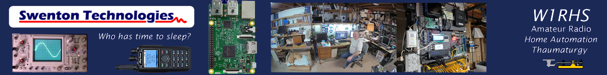
Click here for more Ham Radio Articles on this Site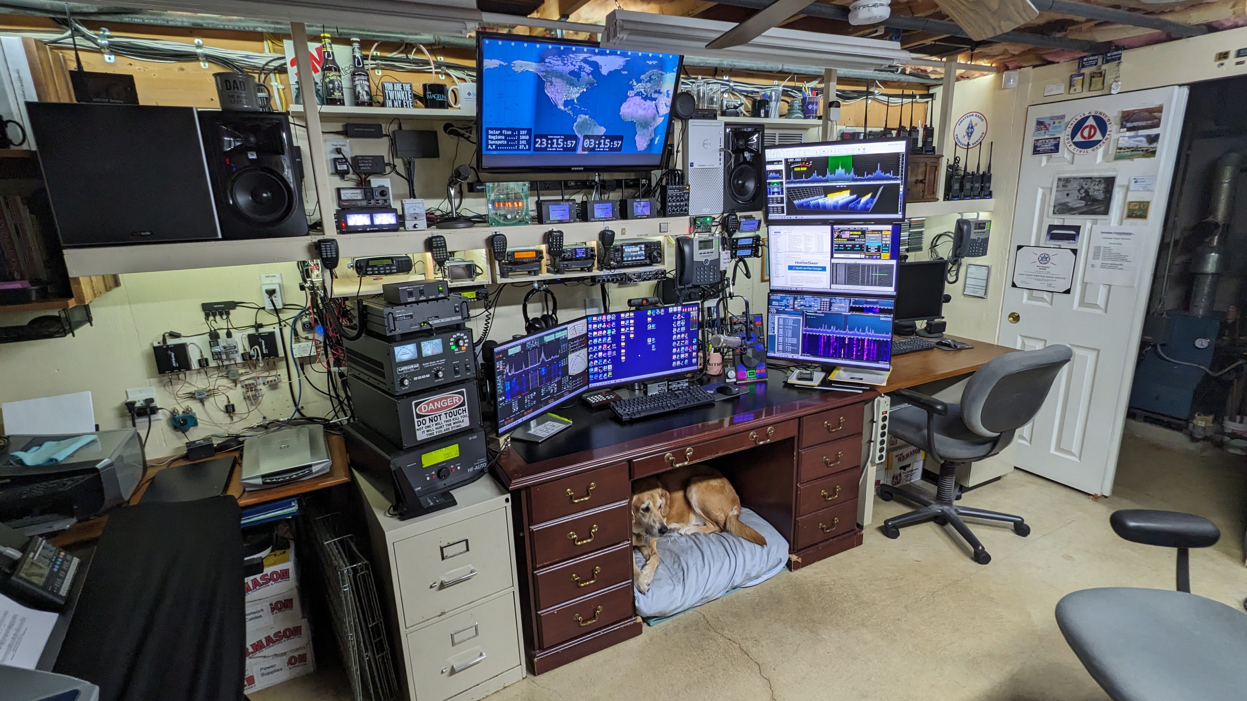 This is the current state of my Ham Radio Station. Some people have called it a "Buzzing nerve center of wires and static." My rescue dog, Gracie, lives under my desk. It was her choice. Yes, that is an original Civil Defense logo on the wall. As a young ham radio operator I was affiliated with the local Civil Defense, American Red Cross and the Civil Air Patrol. I was certified in fallout shelter management and radiological monitoring. Back then, we thought it was possible to survive a nuclear war. We could ... for about a week or two.
On the left side of the wall are the SDRPlay RSPdx and RSP2 receivers along with two RTL-SDR Blog3 and two RTL-SDR Blog4 receivers. The V3 receivers are used with Unitrunker software for trunk tracking the local public safety system. The Hermes Lite 2, Anan 7000, Ameritron 1306 Amp and Palstar HF-Auto Tuner are all stacked up on the left side. Across the top shelf are a Motorola CDM-1500 MMDVM Hotspot, several VHF transcievers and the ICOM 7300. Next is a Connect Systems 800D with BFD screen and two TYT 9600 DMR transceivers.The controller between the displays is a midi controller that can operate the Anan. The controller below the right monitors is a midi controller for the Hermes Lite 2. The Anan, Hermes Lite, 7300 and DMR radios all share the Electrovoice RE27 mic on the desk. Some of the radios share the JBL powered speakers with the Polk sub-woofer. Most of the radios share the RE-27 microphone.
Here's a closer view of the station. There is a Numitron Digital Clock on the top shef. Three Hotspots with Nextion displays are next followed by an audio mixer for the speakers and the station Dell PC. The speaker audio mixer provides individual volume controls for the PC, streaming audio client, Alexa speaker, bluetooth receiver and all the radios that share the powered stereo speakers and subwoofer. The box below the center monitor has a PTT switch. The PTT switch can key any of the radios by selecting the radio with the rotary switch on the left. The microphone line amplifier splits the RE-27 microphone line level audio into four transceivers with volume controls for each.
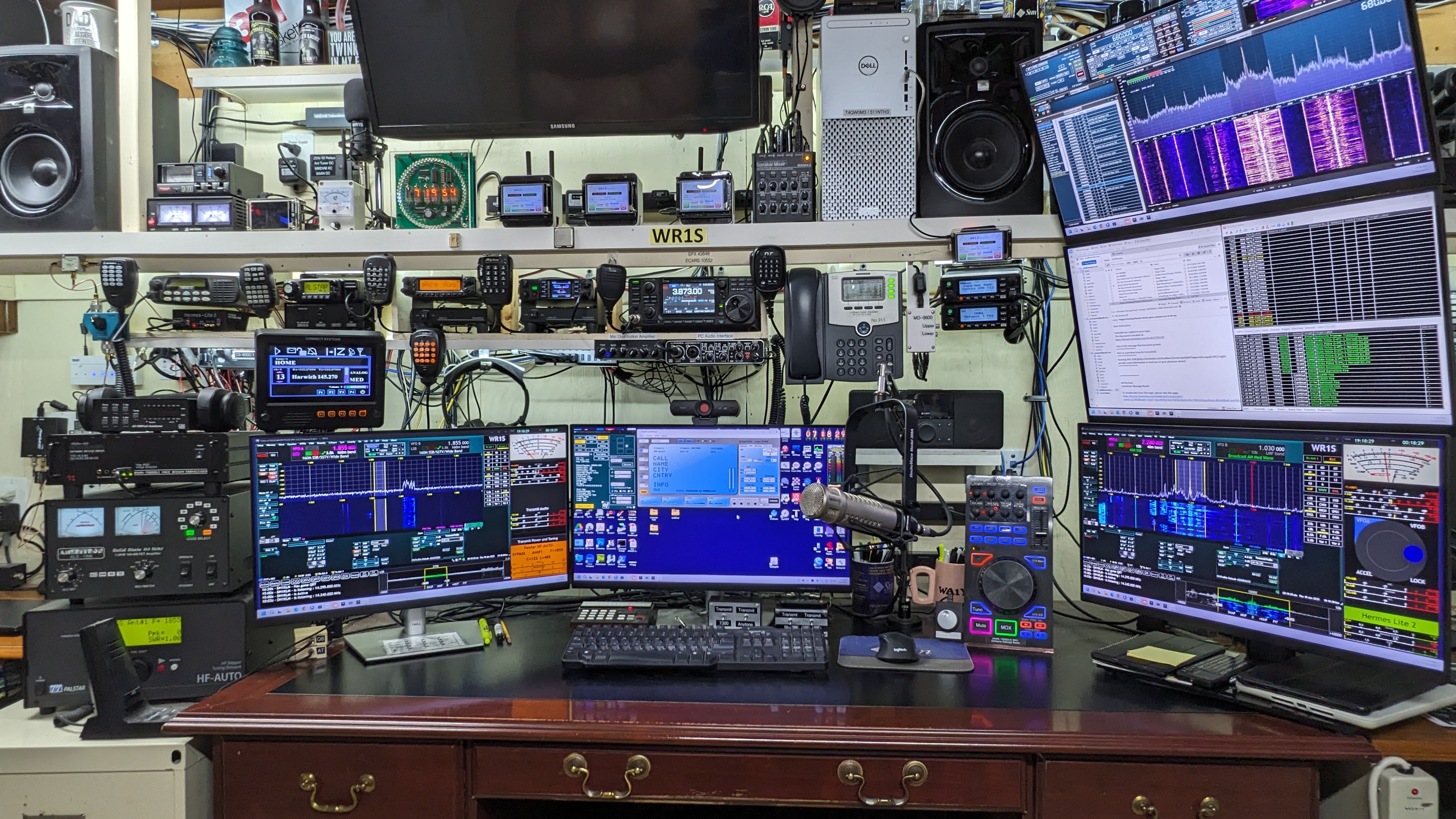
 This is the other side of the workshop where all the fabrication and repairs happen. Should any apparatus, electronic, mechanical, optical or chemical device become discombobulated, this is the place where the device can be expertly recombobulated. As the grandchildren get older, we will be building all kinds of Arduino and Raspberry Pi based projects together. I don't have any RoHS solder. I am still working off my dad's stash of 60/40 Tin/Lead rosin core. Sometimes I need a little help from my friends using the power tools.
Equipment
• Apache Labs ANAN-7000DLE MKII SDR Transceiver 160-6m
• Behringer CMD PL-1 Midi Controller
• Ameritron ALS-1306 1200 watt Solid State FET Amplifier 160-6m
• Palstar HF-Auto Autotuner 160-6m
• Electro-Voice RE-27 N/D Microphone with Cloudlifter CL-1 Preamplifier
• Behringer UMC204HD USB Audio Interface
• Hermes Lite 2 SDR Transceiver 160-10m
• ICOM IC-7300 SDR Transceiver 160-6m
• Yaesu FT-8900R, TYT MD-9600, Anytone AT-D578, Connect Systems CS-800D VHF/UHF Transceivers
• SDRPlay RSPdx and SDRPlay RSP2 Wideband Receivers [RSP2 Article]
• Anytone AT-D878UV, Airiton DM-168, ICOM T90, Wouxun KG-Q10H, Quansheng UV-K1, Malahit DSP-2 handhelds
OpenGD77 Firmware
I am one of the original Alpha Testers for the OpenGD77 Project and continue as Alpha Tester for the followiing radios:
• TYT MD-9600, Radioddity GD-77, TYT MD-UV380 and Retevis RT3S.
I was working with Roger Clark as a tester in 2018 before OpenGD77 was actually a project.
Thetis SDR Software
I am a member of the testers group for Thetis Development by Richie, MW0LGE.
DIGITAL HOTSPOTS AND ANALOG NODES
• High Performance Hotspot STM32-DV MMDVM Controller on Raspberry Pi with Motorola CDM-1550 UHF transceiver, 1 to 30 watts
• Various MMDVM Simplex and Duplex Hotspots on Raspberry Pi with WPSD Digital Voice Software Project
• AMBE Servers for Windows and Raspberry Pi with Northwest Digital ThumbDV Vocoder and ZUMRadio AMBE Server
• Allstar SHARI UHF Node
ANTENNAS (limited space)
• 160m - 10m Inverted-L
• 160m - 10m Receiving Loop
• Discones for VHF/UHF
• Diamond 6/8 wave (2m), 5/8 wave (70cm) verticals
Hangouts:
Operating from Cape Cod on the low bands.
For VHF/UHF Analog and Digital Modes see below. My DMR ID is 3109921. Allstar Node is 522710.
| Location | Frequencies In/Out | Mode | Talk Group |
| Bristol CT | 443.875 MHz / 448.875 MHz Brandmeister, Color Code 1, Time Slot 2 I operate on this repeater with a hotspot or computer. This is my primary hangout. |
DMR | 31094 CDRA |
| Bristol CT | 145.14 MHz / 144.54 MHz I operate on this repeater using a computer. |
D-STAR | REF69C |
| Barnstable MA | 52.01 MHz / 53.01 MHz Tone 173.8 Hz. | FM | |
| Barnstable MA | 146.73 / 146.13 MHz Tone 67 Hz. | FM / YSF | |
| Dennis MA | 146.955 / 146.355 MHz Tone 88.5 Hz. Echolink 20024 |
FM / YSF | |
| Dennis MA | 146.925 / 146.325 MHz Tone 114.8 Hz. | FM / YSF | |
| Dennis MA | 144.97 MHz / 146.46 MHz DMR-MARC, Color Code 11, Time Slot 2 |
DMR | 8804 Cape-Net |
| Harwich MA | 224.34 / 222.74 MHz Tone 100.0 Hz. | FM | |
| Harwich MA | 145.27 / 144.67 MHz Tone 67.0 Hz. | FM | |
| Truro MA | 147.255 / 147.855 MHz Tone 67 Hz. Echolink 403358 Allstar Node 532900 |
FM | |
| Harwich GMRS | 462.725 / 467.725 MHz Tone 114.8 Hz | FM | |
| Falmouth GMRS | 462.675 / 467.675 MHz Tones 141.3 and 67.0 Hz | FM | |
| Digital Radio Networks | |||
| CDRA | Connecticut Digital Repeater Assn.on Brandmeister | DMR | 31094 |
| OpenGD77 | OpenGD77 on Brandmeister | DMR | 98977 |
| BARC | Barnstable Amateur Radio Club on Brandmeister | DMR | 3130258 |
| STEM | North Star Digital Net on Brandmeister | DMR | 31630 |
| NEDECN | New England Digital Emergency Communications Network DMR-MARC Repeaters on Cape Cod in Bourne, Dennis, Eastham and Falmouth MA |
DMR DMR |
8804 CapeNet 3181 New England |
| Allstar | Allstar Node | FM | 522710 |
| HoIP | Hams over IP VoIP Phone | Ext | 102422 |
 |
Memberships Barnstable Amateur Radio Club on Cape Cod Pilgrim Amateur Radio Club on Cape Cod New England Digital Emergency Communications Network Lonely Guys Net #485 American Radio Relay League (ARRL) East Coast Amateur Radio Service (ECARS) #10552 |
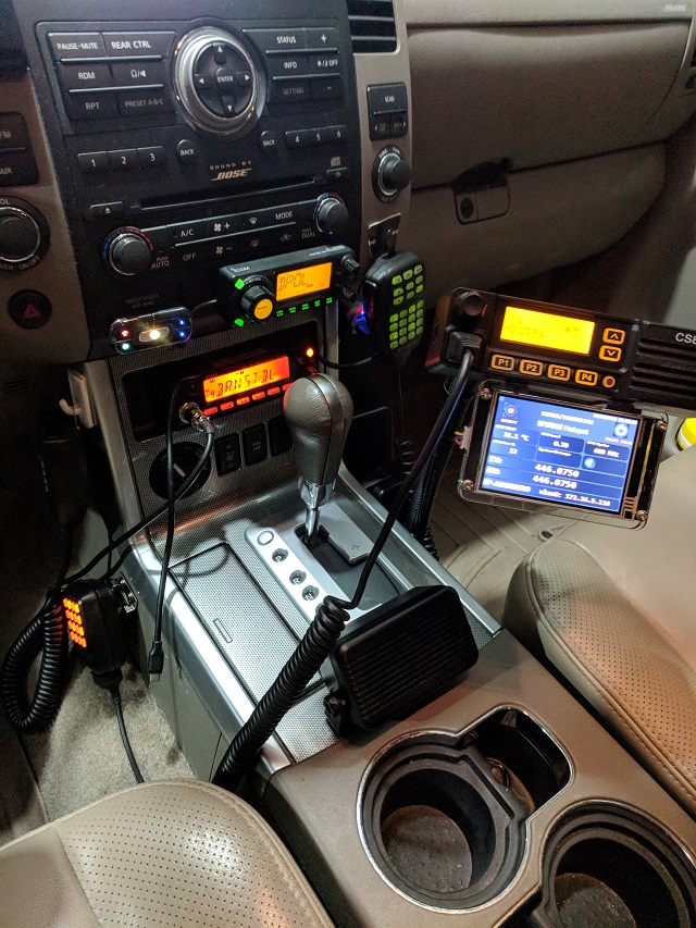
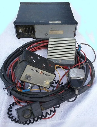
My previous mobile installation on 6M, 2M and 440 MHz FM and 2M and 440 MHz DMR. Unfortunately, 440 MHz repeaters are mostly not allowed on Cape Cod because of the Pave Paws Air Force Radar System at Otis Air Force Base. My installation includes a mobile DMR hotspot. I remotely mounted the hotspot display under the radio control head.
I have been using DMR for many years, but I was first on NXDN because of my affiliation with a two-way radio shop and access to the equipment. Evans Mitchel, KD4EFM and I established the first NXDN internet contact between two NXDN repeaters, K1IFF/R in Connecticut and N4KEG/R in Florida back in 2012. This was before the NXCore and NXRef reflectors were available. It was a direct link between the two repeater routers over VPN.
I was one of the original alpha testers for the OpenGD77 firmware for the Radioddity GD-77, Baofeng DM-1801 and RD5R DMR Radios. I am also an alpha tester of the OpenGD77 firmware for the TYT MD-UV380, RT3S and TYT MD-9600.
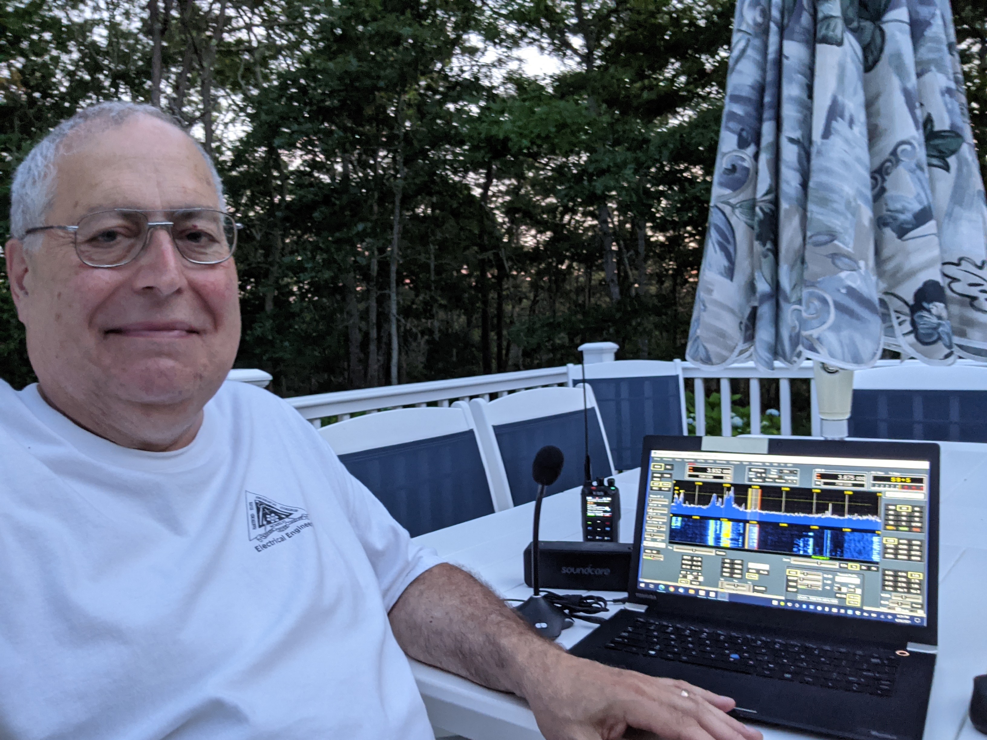
Summer is the perfect time to make some contacts while relaxing on the deck. I use a bluetooth music speaker so I can get fairly good high fidelity sound. Here, I am using a small computer electret condenser mic. I also have a USB studio condenser mic for remote use. Mic and speaker audio are sent over the network using the virtual audio cable support in the Thetis control software. All of the radio's controls are available on the laptop.
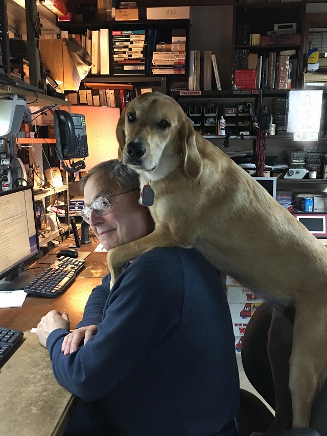
Gracie is my rescue dog from Arkansas. She sleeps in her favorite place under my desk. She never barks or otherwise interrupts the important radio transmissions emanating from this station.
I was a Repeater Builder in the Hartford CT area from 1974 through 2003. I was responsible for the tube to solid-state transition of the WR1ABM 28/88 repeater in Avon CT, adding a solid-state UHF RCA 1000 series repeater and adding a new VHF repeater with 6-meter Remote Base, WR1AFU 75/15 in Burlington CT back in the late 1970s through 1980s for the Insurance City Repeater Club. From 1978 to 2003 I had my own repeater, WA1LMV/R, formerly WR1AIB, simulcasting on 447.925 MHz and 53.01 MHz also in Burlington, CT.
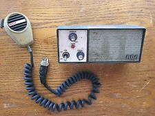 RCA Series 700/1000 Control Head RCA Series 700/1000 Control Head |
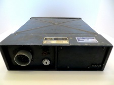 RCA Series 700/1000 Radio RCA Series 700/1000 Radio |
 RCA VeeTac Control Head |
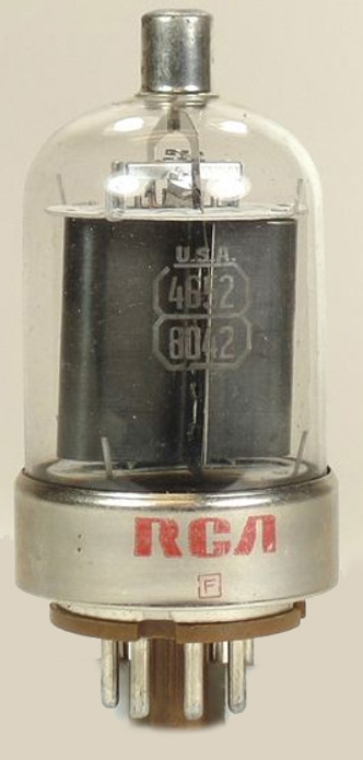 |
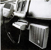
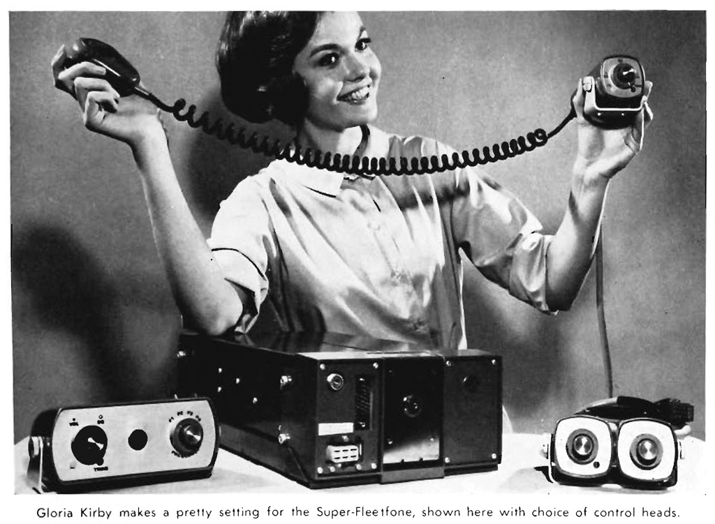
In those days we had access to used RCA land mobile radios. Our repeaters were built from RCA Series 700, 1000 (left, middle) and Veetac radios (right.) I had some older RCA mobile radios in my car. I had Super -Carfone and Super-Fleetfone models. The Super-Carphone had directly heated cathodes in the 8042 tube finals. They could deliver 30 watts per tube. The tubes heated within one second and you were ready to transmit when you lifted the mic from the cradle. The later Super-Fleetfone models were all solid state, but the UHF model used a varactor tripler. 45 watts from the VHF final transistors yielded only 15 watts from the varactor. These models were power hungry requiring thick cables from the battery to the trunk. The car headlights dimmed when you transmitted. The RCA radios were easy to modify. There were no edge connectors. The circuit boards were interconnected point-to-point with pins on the boards and push-on wire connectors. It was easy to tap into things like COS, TOS and PTT lines. I had several RCA Tac-Tec handheld radios.
|
My own 6 Meter / UHF repeater, originally WR1AIB and later WA1LMV/R, went on the air in Burlington CT on 52.01/53.01 and 442.925/447.925 in 1978 and was decomissioned in 2003. The first 6-meter repeater was built using a GE Master Executive shown above. These radios were obtained after the local police department converted from Low Band to 800 mHz. The second 6-meter repeater was built using an RCA 1000 Series. The UHF repeater was built from an RCA Veetac. You can learn quite a bit about operating a repeater by running one on 6 Meters. There are challenges with desense and tower noise that are much worse on 6 Meters than on the upper bands. Let's not overlook the additional RFI related to electric fences on the farm. I am so grateful to my friend, Don, K1ZSG, for sponsoring the site, power, tower and most of the equipment for all those years.
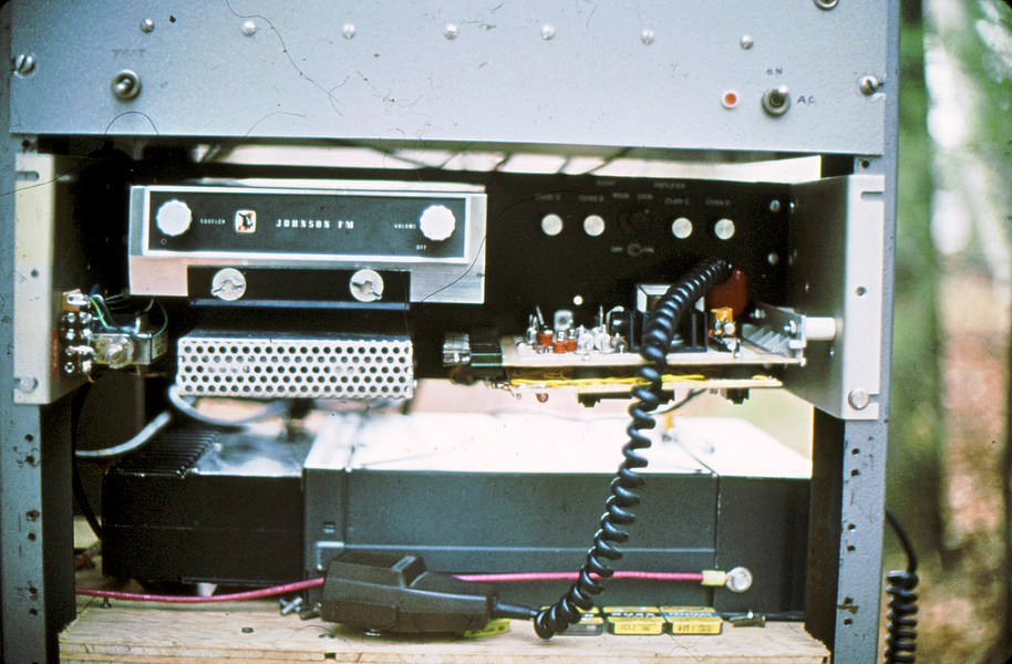
This is the first iteration of the solid state conversion of the WR1ABM repeater in Avon, CT. It used a Johnson VHF mobile radio with a small TTL controller board and a simple audio mixer. Below the Johnson is the RCA 1000 series mobile that was the UHF repeater. Click Here for the WR1ABM/R Photo Gallery from the mid 1970s.
I operated my own cross band repeater system between 1977 and 2003 in Burlington, CT.
WA1LMV/R - Burington, CT
On the air in 1978 as WR1AIB.
52.01 MHz. In / 53.01 MHz. Out
crosslinked to
442.925 MHz. In / 447.925 MHz. Out
This repeater used a personally designed and built 8085 controller. The hardware and software is full-featured. The controller supports speech, accessories, time scheduling, autopatch with speed dialing, radio and landline control, remote bases, diagnostics, video display terminal, and much more. I could even turn on the flood lights at the repeater site while driving in.
I wrote the 140 page software program in Z80 assembly language. It assembles down to a 17k machine language program in EPROM. The software is a full-blown real time operating system with 5 hardware interrupt levels to simultaneously process DTMF commands from the receivers, DTMF commands from the phone line, buffered type-ahead commands from the terminal keyboard, background timer processing interrupt, real-time error trapping (boundary checking for program counter and stack pointer) and a fail-safe heartbeat interrupt. It had Autopatch and Reverse Autopatch. Here is the source code (text file) in case you are interested.
 Here's the User's Manual.
Here are the features in detail:
- Two main receiver inputs for COS and PL
- Two aux receiver inputs for COS
- Audio gate control outputs to control the mixer gates
- Two main transmitter outputs
- Two aux transmitter outputs
- MCW messages and ID with programmable speed and pitch
- ID Timer with polite ID and broadcast ID
- Phoenemic based speech synthesizer with unlimited vocabulary
- Separate main receiver time-out timers with PL override
- Separate main and aux receiver timers for access and release delays
- Aux transmitters inactivity dump timers
- Autopatch with inactivity dump timer
- DTMF regeneration and speed dialer with speech readout
- DTMF mute of audio gates
- Reverse autopatch with announce
- Dial-in landline system control
- Courtesy tones with programmable MCW character and pitch
- Aux receiver and transmitter status tones
- CRT console with command line, menu, status display and type-ahead buffer
- Full control over any input or output
- Interrupt driven background processing system
- Polling foreground priority based task driven master processor
- Two interrupt driven DTMF decoders with buffered type-ahead
- Watchdog timer / fail-safe processor in hardware and software
- Time of Day alarm clock / calendar with hourly chime, speech readout and event scheduling
- Programmable macro commands for speed key commands.
- Direct memory access through console or DTMF with speech readout
- 2m Remote base synthesizer control with programmable frequency banks, mode and power control
- Detects presence of TOD clock chip and emulates functionality in software if not detected
During the winter of 2003, the tower guy wires were hit by a tree branch that had fallen during an ice storm. The guy wire broke and the tower came down. Fortunately nobody, including the residents of the associated house were injured. The tower fell in an optimal direction. It was time to clean house at the site to make way for paying customers.
Thanks to my friend Don Nelson, K1ZSG, for his assistance and generosity for all these years.
Repeater Microprocessor Controller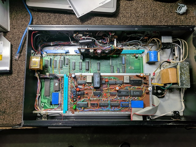
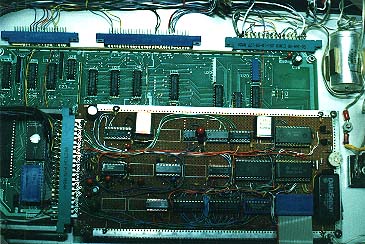
Here is the top view of the controller. It is a surplus single-board 8085 based computer with a 5 Mhz clock. It was removed from a Kodak Ektachem Blood Analyzer during an upgrade. The board can accept an 8K, 16K or 32K EPROM and has four memory-mapped 8-bit output ports and three memory-mapped 8-bit input ports (not including the I/O ports on the PPI) along with 4K of Static Ram. In order for me to use this board, I had to learn how to program the 8253 Programmable Interval Timer (PIT), the 8255 Programmable Peripheral Interface (PPI), the 8259 Programmable Interrupt Controller (PIC), and the 8251 Universal Synchronous/Asynchronous Receiver-Transmitter (USART). Learning how to initialize those and program to work with this board was no trivial task. I had to use the schematic to identify the addresses of the support chips and I/O ports. Above the main board is a custom I/O expansion board with a time-of-day clock with battery backup, an SSI-202 touchtone decoder, an SSI-75T2089 touchtone encoder/decoder, a watchdog timer, a tone generator, an SSI-263 speech generator and several I/O ports. I had to learn how to program the SSI-263 phoneme-based speech synthesizer which speaks words and phrases by combining phoneme sounds.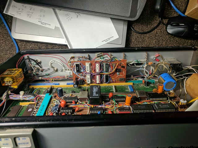
On the back edge of the cabinet there is a small analog-to-TTL input board. This board has transistor arrays in 14 pin DIP packages, pull-up resistors, inverters and DIP switches. This is a universal receiver to controller interface. Each input is a 0 to 15v input which produces a 0 to 5v TTL signal. The DIP switches can program an inverted signal polarity. This is used to connect the receivers' COS, TOS and other signals to the controller.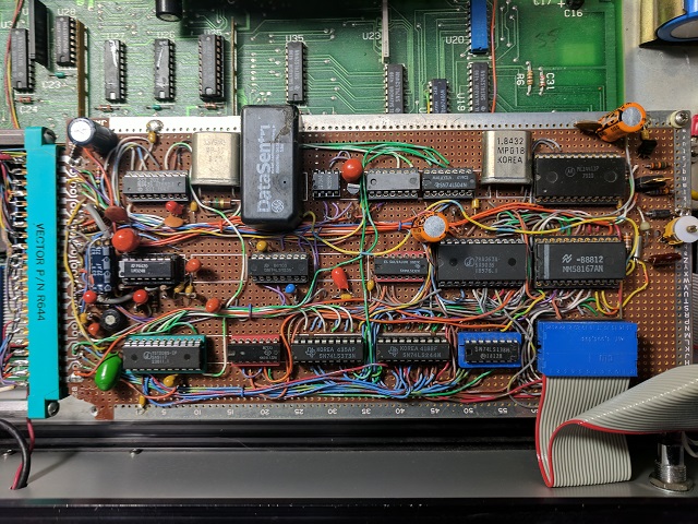
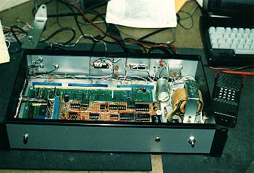
This is the inside view. The 8085 CPU board was salvaged from a Kodak Blood Analyzer. I re-programmed the board from scratch adding hardware on the proto board that included a speech synthesizer, time of day clock, a DTMF encoder/decoder, a DTMF decoder, battery backup, watchdog timer, baud rate generator and more. I wrote the firmware in Z80 Assembly Language using only the Z80 instructions that had equivalents in 8080/8085 Assembly Language. I wrote the program using a HealthKit H89 computer and programmed the controller using a homemade EPROM programmer. I built an Ultraviolet EPROM Eraser using a bathroom germicide UV lamp and a small florescent ballast salvaged from an old desk lamp.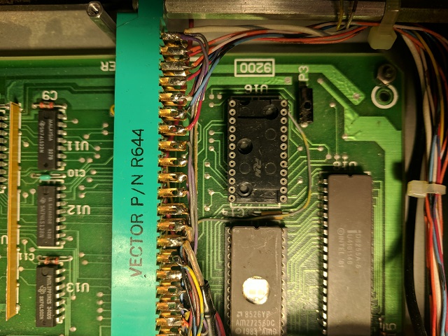
In order to easily interface to the main board I soldered a 28 pin DIP socket to the top of the static RAM chip. This gave me address, data and control lines that I could bring to the expansion board with a ribbon cable.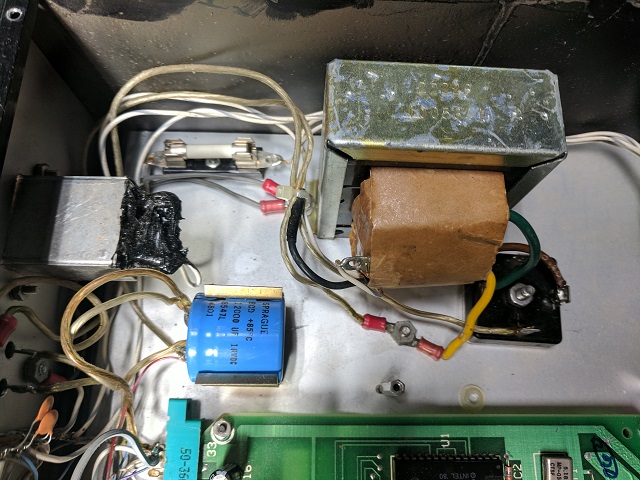
The power supply was a simple analog supply with a 5v regulator. The power cord receptacle was an EMI filter with exposed solder lugs. I coated the lugs with black RTV for shock protection. Apparently, I was not worried about the connections on the fuse.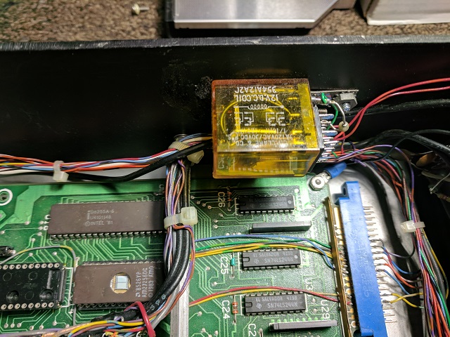
Some things could not be totally solid-state. The only relay was for telephone line access.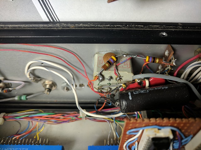
Besides the power supply transformer there was one other transformer, a 600 ohm one to interface to the telephone line.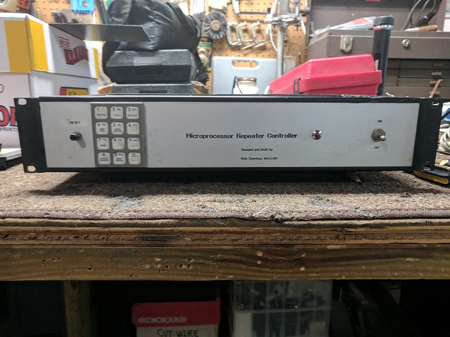
Here's the front panel. Power switch, power indicator, touchtone pad and reset button.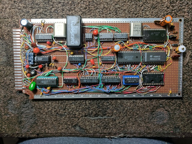
Finally here's a picture of the expansion I/O board. Notice the 28 pin DIP socket in the lower right. That's where the ribbon cable plugs in and connects to the corresponding socket on the CPU board. The variable capacitor on the right was to trim the watch crystal for the time-of-day clock. The 1.8432 MHz crystal was for the baud rate generator for RS232 serial communication. The crystal near the rechargeable battery is a 3.579 MHz color burst crystal for the touch tone encoder/decoder chips. On this board is an SSI273 Speech Systhesizer. I had to learn how to program it. The speech had unlimited vocabulary because it was programmed using phonemes. I had to "teach" the speech synthesizer every word by stringing phonetic syllables and then adding volume, duration and pitch inflections. Also on this board is a DTMF decoder, a DTMF decoder/encoder and the Watchdog Timer. Unfortunately I can't seem to locate the diagram for the expansion board.
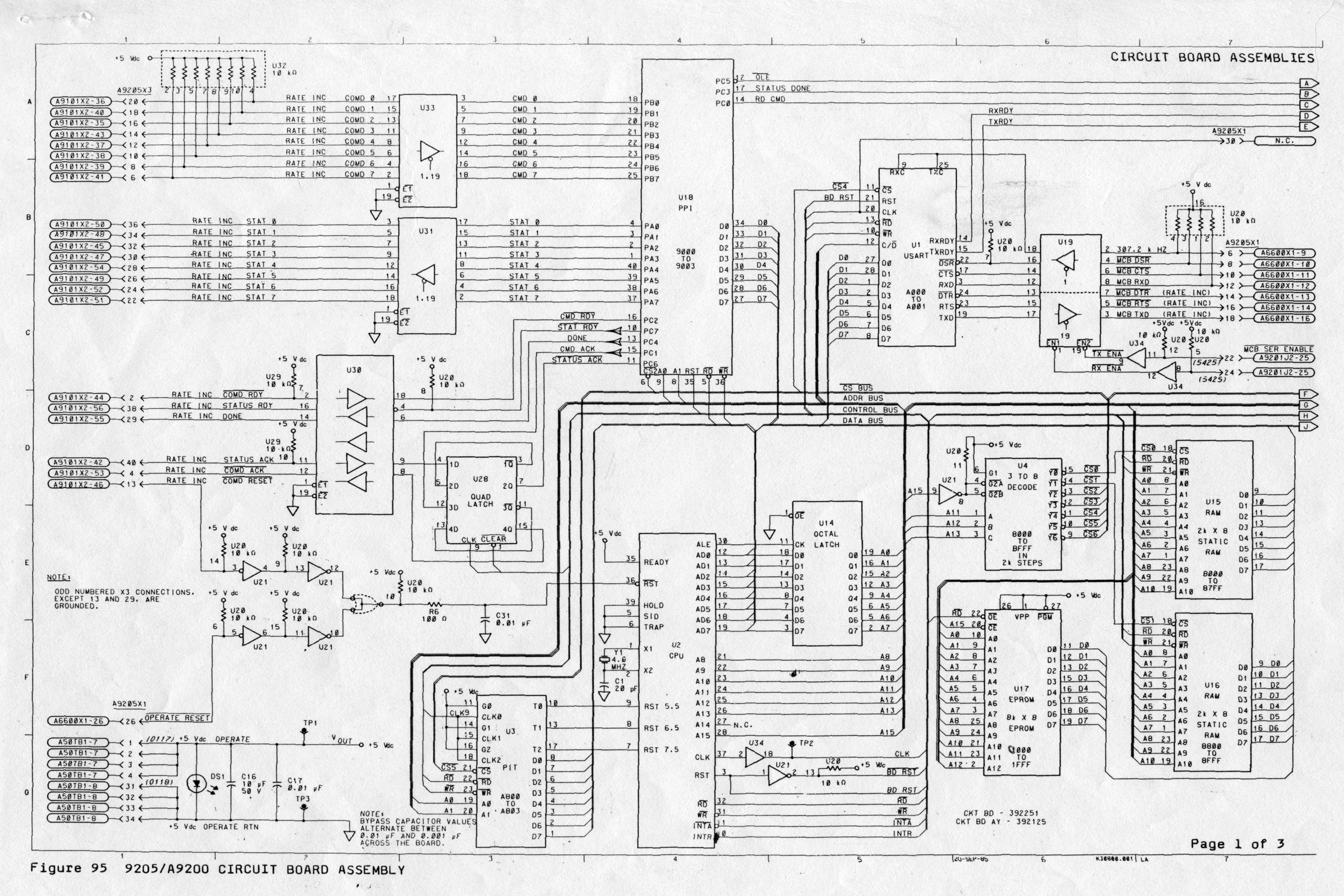
The CPU board was a PCB that came from a Kodak Ektachem Blood Analyzer that was discarded after an upgrade. These three schematics were all I had to work with in order to write the firmware.
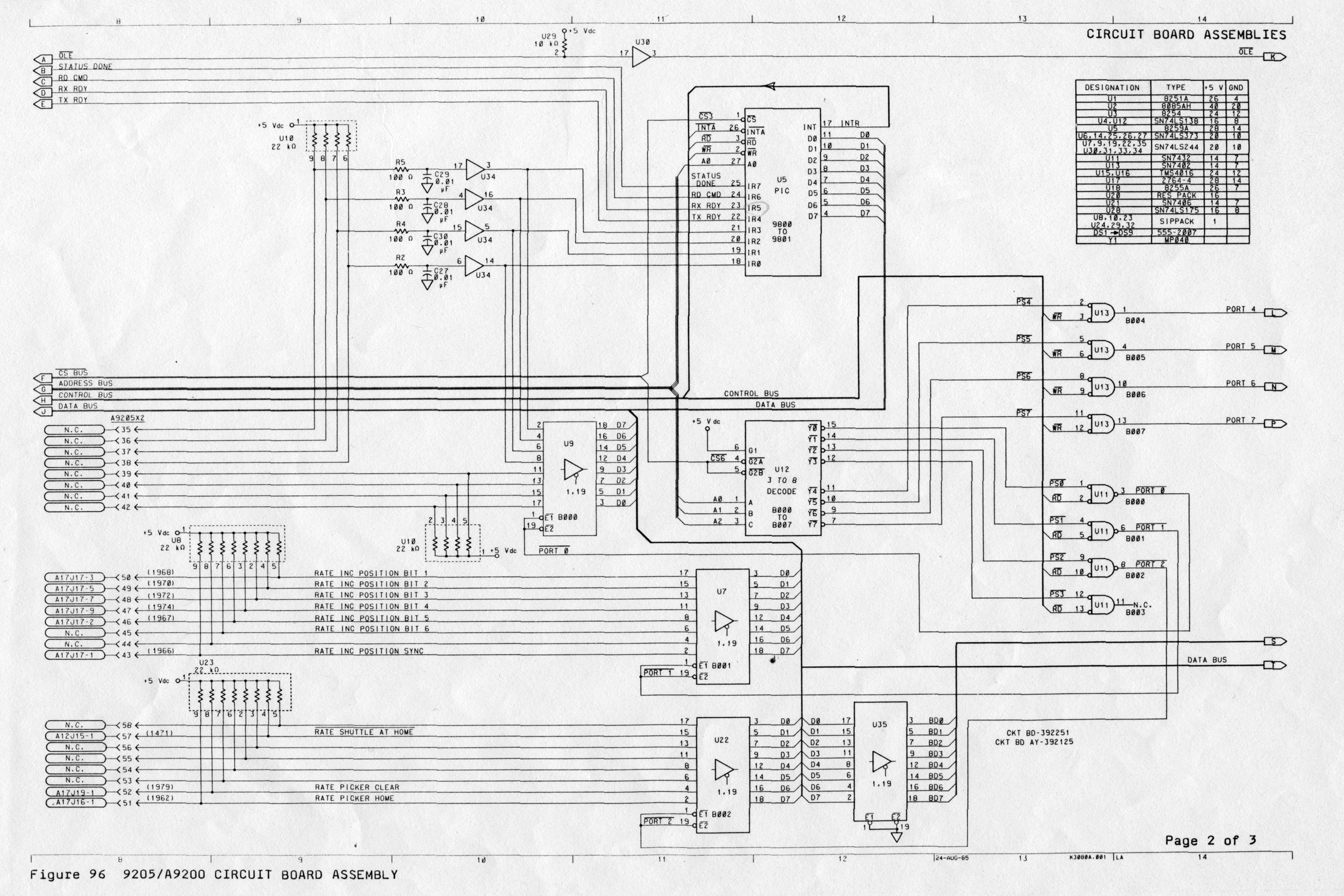
The board can accept an 8K, 16K or 32K EPROM and has four memory-mapped 8-bit output ports and three memory-mapped 8-bit input ports (not including the I/O ports on the PPI) along with 4K of Static Ram. The board was designed for an 8K EPROM. By cutting one trace and adding one wire I converted the board to use a 32K EPROM. In order for me to use this board, I had to learn how to program the 8253 Programmable Interval Timer (PIT), the 8255 Programmable Peripheral Interface (PPI), the 8259 Programmable Interrupt Controller (PIC), and the 8251 Universal Synchronous/Asynchronous Receiver-Transmitter (USART). Learning how to initialize those and program to work with this board was no trivial task. There are no IC Device numbers on the diagrams. All that's shown is the function of the IC such as CPU, EPROM, RAM, PIT, PPI, PIC and USART. A bit of helpful information is that some ICs show their address range on the diagrams. I placed a lot of information about the ICs and the PCB as comments in the source code. Having already owned and built my Heathkit H89 computer, it was not extremely hard to understand how this board worked. The hardest part was learning how to program the 82xx series support ICs from scratch. I was fortunate to have the Intel IC Databooks which had all the needed information.
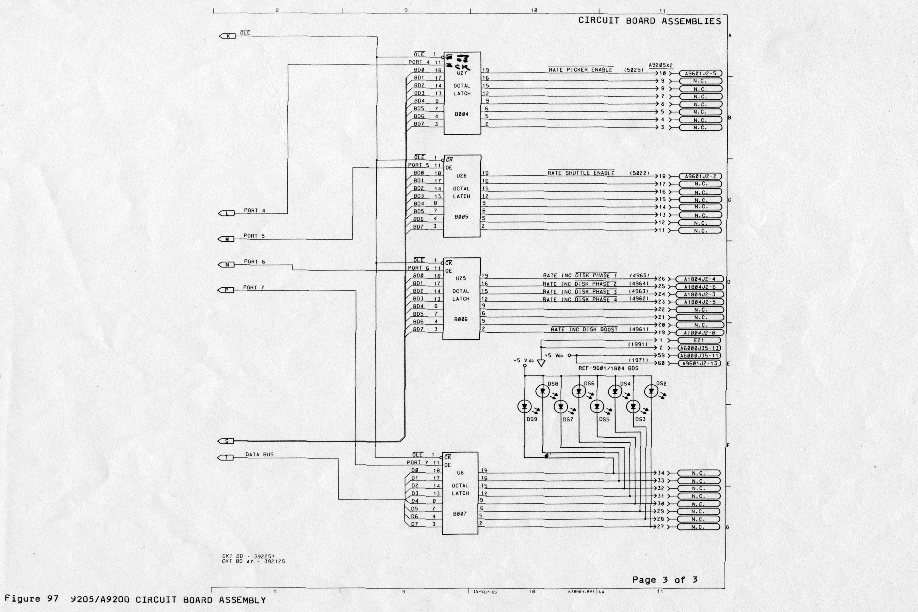
I scanned these images from photocopies in my archive. From the fine print in the diagrams you can see these were created by Kodak in 1985. You can click on any of the diagrams to see a higher resolution image. I learned so much as a Field Engineer with Kodak. My Field Service work and Ham Radio Hobby overlapped every day.
Here is the firmware source code (text file) in case you are interested.
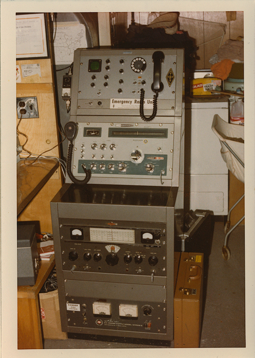
Here are a few pictures of the decommissioned equipment arriving at my house along with some old pictures of when the system was in service.
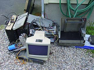
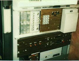
Two 20 Amp power supplies (left) under the keyboard, the ADDS 2020 CRT monitor (center), the RCA Series 1000 Low Band Transceiver below the CRT, and the microprocessor controller and audio mixer (right). The 20 Amp power supplies were huge and heavy. They were a conventional analog design with six 2N3055 pass transistors and large heat sinks.
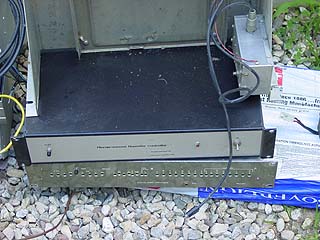
Controller (top) and mixer (bottom).
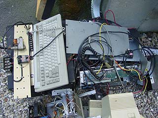
Top View of the heap.
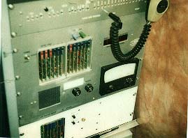
A "pre-micro controller" picture of the rack sometime around 1990. At the top is a custom antenna rotator controller that runs an Aliance U100 motor. It takes commands from the logic system and can position the motor from 0 to 360 degrees in 10 degree increments. Next is a rack mount RCA SuperFleetfone low band receiver followed by the 16 channel audio mixer. This custom designed audio mixer actually contained the receiver squelch gates which were solid state switch ICs. All the small holes in the front panel are to insert a small screwdriver to adjust the trim pots that control the gain of each channel. The two main receivers had three squelch gates each. One was to gate the repeat audio. One was to gate the audio going into the autopatch. The other was to gate the audio going into the DTMF decoder. Having a seperate autopatch gate allowed DTMF tones to be heard by the phone line while the repeat audio remained muted. Having a sepaerate DTMF decoder gate allowed the DTMF decoder to hear DTMF tones even when there was no CTCSS tone on the input. The microprocessor software decided on which gate or gates to open at any given time. The other trim pots were for adjusting thing like TX line audio, MCW ID, Speech, tone prompts, remote base receivers and even the local mic.
Before the microprocessor controller, there were 15 logic boards controlling the system. From top to bottom: The 16 channel custom audio mixer, two banks of 5 logic boards. The first 5 are the repeater logic, the second 5 are the control system. A bank of 5 more boards in the white panel were expansion functions. The binding posts above the main logic rack are +5V and GND for the Logic Pen. (Remember those?) I had a board extender so I could operate each board extended out of its slot for troubleshooting.
The older system had a Teltone 3-board DTMF decoder and a Wescom Hybrid for the Autopatch. These were commercial telephone company grade components. The Teltone decoder was eliminated when I added the microprocessor controller. Below that is the two meter remote base consisting of a Standard HT transceiver board and a GLB Synthesizer interfaced to the repeater logic. Last is the GE MASTR Royal Exec transceiver, the original 6 Meter repeater receiver and transmitter for 52.01 / 53.01 MHz.
Development of the new controller hardware on the bench. The controller could accept ASCII control input simultaneously from the CRT keyboard, DTMF from two radio receivers and DTMF from the phone line. Software was written on the Heathkit H89 computer in Z80 Assembly Language. The 140 page program assembled down to 17 kilobytes to fit in an EEPROM. I built an EEPROM programmer to work with the H89 computer. I built an Ultraviolet EPROM Eraser using an ultraviolet bulb intended for a bathroom germicide device. These bulbs look like florescent bulbs but with a clear glass envelope. There's no white frosting on the inside.
Inside view of the controller. The computer board (the lower one) is a control board from a Kodak blood analyzer. It has an 8085 µP running at 5 MHz, up to 64K of EPROM and plenty of I/O ports. The upper board is the additional circuits that adds a DTMF decoder, a DTMF encoder/decoder, speech synthesizer, time of day clock, watchdog timer and audio tone circuits.
View of the controller under construction. Notice the Icom IC-4AT handheld radio and the ADDS Viewpoint terminal on the right.
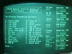
Screen shot of the video display from Feb. 23, 1991. Notice the single letter control command menu, the display of the various timers, and the display of the I/O port signals shown as ones or zeros. When the controller was running, this screen provided a real-time display of the various signals. The ID Timer, receiver Time Out Timers, the Transmit tail timer and date and time all showed updating on the screen. The ones and zeros on the right side reflect the various signals like receiver COS, TOS, PTT and more. Each set of signals had two rows. The top row is the control bits. The bottom row is the status bits. The status bits come on and off as the inputs change or as the controller changes output bits. However, the signal will only be processed if the control bit above the status bit is set by the control system. The control system can enable or disable any individual signal by changing the control bit. The display was an ordinary dumb serial terminal running at 19,200 baud. It looked like a video raster because I performed direct cursor addressing with the cursor turned off. When the processor booted up, the static text on this screen is written once. Then about once per second, only the data that changes is written to the screen using direct cursor addressing. In what appears to be in real time, the clock and timers change. The ones and zeros that indicate the various repeater statuses appear to change in real time. Option X in the Menu will refresh the static text should the screen get messed-up such as from a power outage.
Here's a blast from the past. This is my Ham Radio Shack as it appeared in 1973. Starting at the top left corner is a barely visible Heathkit Mohegan shortwave portable. Next is a Heathkit Signal Generator. The black panel with the six knobs is a stereo tube type homemade stereo tube amplifier connected to the adjacent HH Scott FM tuner with a homemade stereo demodulator. On the middle shelf is a homemade oscilloscope and phone patch console, a low band 30-50 MHz tunable monitor, and a Glalaxy FM-310 three channel cyrystal controlled 2M FM transceiver. On the bench is a National NC-270 Ham Band receiver. On the table on the right is a Polycom 6M AM transceiver, an SBE-33 HF SSB transceiver, A Halicrafters SX-99 Shortwave receiver and finally a Heathkit Marauder HF SSB transmitter. Under the bench visible behind the chair is a Collins 32V1 HF AM transmitter. Thank God my Dad was generous with the precious space in his small workshop!
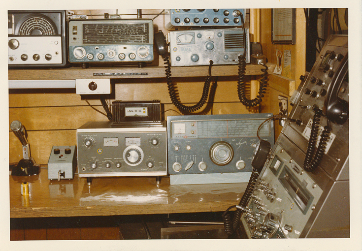
Later I installed some of the equipment into a nice 19 inch rack cabinet/desk on the right. Notice the Heathkit electronic keyer and the mechanical 24-hour digital clockm set to GMT, of course. This was a nice station in its day. It was all used equipment when I got it. On the top shelf, L to R, is a Hallicrafters SX-99 shortwave receiver, a Heathkit Mohegan portable shortwave receiver and an SBE-33 80 through 10 meter SSB base/mobile transceiver. On top of the SBE-33 is a Polycom 6 six meter AM transceiver belonging to the city's Civil Defense. On the bottom shelf is a Trio receiver (before they changed the name to Kenwood) and a National NC-270 receiver.
This is the transmitter array with the Heathkit Maurader and the Collins 32V-1. The home-made oscilloscope and phone patch are at the top. An adjustable regulated power supply is at the bototm.
 This is a photo from around 1972. I still have that GE soldering iron that is powered by the black transformer. Behind it is a Weller battery operated soldering iron not commonly found in a home hobbyist tool collection of the day. This was a time before I became involved with FM and repeaters. Notice the Vibroplex semi-automatic paddle on the desk. See the description below.

While I mentioned I was not a fan of Morse Code and the CW mode of transmission, I do have a very nice Vibroplex Original Deluxe "Bug." These are semi-automatic keys used to send high speed code. The Bug is operated by your thumb on the wide red paddle and your first two fingers on the small round red knob. Morse Code is sent by moving the paddle and knob horizontally left and right. A dash is sent manually by pressing your fingers to the left. Dots are sent automatically by holding your thumb to the right. When the paddle is held in, the long center shaft with the weight at the left end starts to bounce from the spring loading. When the paddle is held to the right, the Bug will start sending a repeating pattern of dots as the spring bounced. The speed of the dots is controlled by adjusting the position of the weight on the shaft. Furthest from the center causes a slower pattern. Closer to the center increases the dot rate. These semi-automatic keys have been around for a long time. The Vibroplex company was started in 1905. This Original Deluxe Bug is still being sold for $290. Mine, obtained from a friend around 1972, is still in great condition.
Today, people use simple paddles that are just switches. They connect to an electronic keyer or to a radio that has a built-in keyer. The keyer is usually microporcessor controlled and provides accurately formed high speed Morse Code generation. Here is a Youtube Video annimation showing how the Vibroplex semi-automatic key works.
Here's a list of all the old Ham Radio and commercial Land Mobile two-way equipment I used to own. As a teen and later as a young adult I did not have much disposable income. Most of the equipment was second hand or surplus.
| Receivers | Transmitters | Transceivers |
| Trio/Kenwood 310 | Collins 32V1 | SBE-33 |
| National NC-270 | Heathkit Maurader HX-10 | Polycom 6 |
| National NC-66 | Johnson Viking-II | Galaxy FM-210 |
| Hallicrafters SX-99 | Johnson Ranger | Regency HR-2 |
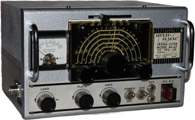
| Hallicrafters S-38B | Multi Elmac AF-67 | Regency HR-6 |
| Heathkit Mohegan | Heathkit AT-1 | Drake TR-22C |
| Hammarlund HQ-180 | Ameco AC-1 | |
| Drake R4C | Drake T4XC | |
| Gonset G-66 | Gonset G-77 | |
| WRL/Globe Chief 90 | ||
| Military Receivers | ||
| BC-348 | ||
| ARC-5 |
||
|
Commercial Land Mobile Radios |
||
| Manufacturer | Model | |
| GE | Progress Line, Mastr, Executive, Royal Executive, TPL, Pacer, Pocket Mate, Porta-Mobile |
|
| Motorola | Motrac, Mocom 70, Micor, HT-200, HT-220, PT-300, Minitor, CDM-1550 (I still have two PT-300 radios) |
|
| RCA | Carphone, SuperCarphone, SuperFleetphone, 700, 1000, VeeTac, TacTec |
|
| Kenwood | NX-220, NX-320 NXDN Handhelds | |
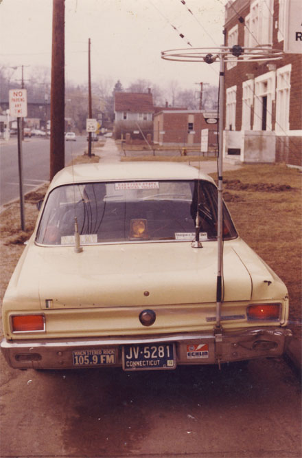
When I was a member of the Bristol CT Civil Defense we operated a 6 meter AM net and I operated from the car. I used a Halo antenna mounted on the bumper of my prestigious 1967 Rambler American (6-Cylinder, 3-Speed manual on the column, no power anything.) I actually commuted to college and was seen in public with this car. Eventually my brother repaired the accident damage and repainted the car the same yellow color. During one summer I replaced the engine in this car at the high school auto shop with the help of the legendary shop teacher, Stanley Sepiol, who passed away on Feb. 24, 2025. RIP Stan!
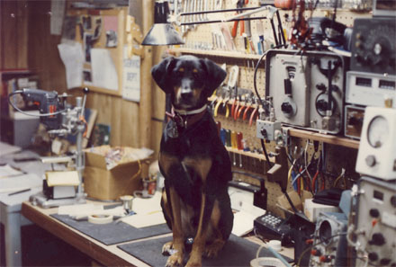
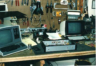
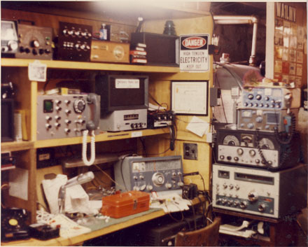
Here's the workbench around 1978 along with my first dog, Brownie. You can see the Motorola signal generator on the top shelf, the Sola Basic wattmeter to the right and the Motorola service monitor on the bottom left. These devices were already old back then.
By this time in my life I became rather proficient in servicing commercial two-way radio products. Besides servicing land mobile radios and converting many to Amateur Radio Service I specialized in repairing desktop paging encoders. These devices look like calculators with a keyboard. They attach to a remote base station transceiver such as found in a police, fire or ambulance dispatch center. When the operator wants to activate someone's pager they enter the code in the keyboard and press Send. The encoder will start the transmitter and broadcast a two-tone code to activate the pager. Then the dispatcher can broadcast the audio message to be heard from the pager. These encoders were connected to the hill-top remote transmitter over a leased telephone line. As such, they were prone to damage from lightning strikes. The bench technician at the two-way radio shop disliked working on these encoders, probably because they generated 90v to send over the phone line and because lightning damage is hard to diagnose. Every week I would go to the shop and retrieve a box of these encoders to fix at home and returned the repaired units the next week. I replaced the components that interfaced with the phone line with heavier duty and more resilient ones. I had hardly any encoders returned to me for repeat service even after lightning storms.
The bench technician also disliked working on Motorola Minitor pagers so I took a weekly box of those home for repair too.
Around 1978 I assisted the radio shop with the transition of the Bristol CT Police Dept. from Low Band (39.42 MHz) to 800 Mhz. In addition to the installation activities, my friend, Cliff, K1IFF and I covered service calls for the Radio Shop when they were on vacation. Some of these calls were operator errors as the dispatchers were learning the new controls.
At that time there were no commercially available police scanners that covered the 800 mHz band. One of the radios in a police cruiser had a melt-down in the transmitter that would be too costly to repair. The whole radio was replaced and I was able to take the damaged unit home to use as a receiver. The police repeater system had a backup transmitter site across town that was turned on with a switch by the dispatcher. One day, while listening, I heard many reports of the officers not hearing the dispatcher or each other. As I listened, I heard a low frequency warble. I recognized this as a heterodyne between two DPL tones. Both repeater transmitters were turned on! I called the shop owner who called dispatch and told them to turn off the backup transmitter switch and everyone was happy again.
The new police dept. installation included the MODAT system shown below.
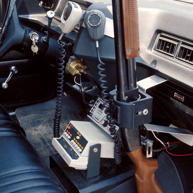
Motorola MODAT is a now obsolete Motorola data system using a sequence of seven audio tones similar to the five-tone-sequential Selcall format. The MODAT unit is the white plastic device with the row of pushbuttons. Each button was defined by the police department to correspond with the vehicle's or officer's status. For example, one button could be labled 10-7 (Out of Service). Another could have 10-8 (In Service). The MODAT system also time-stamped the vehicle's activity and logged this to the dispatch computer. This happened when the officer lifted the mic out of the mic holder. Word got out about the mic holder causing time logging. We frequently got services calls for failed logging. We found the mic sitting on the seat and quarters or nickels were inserted into the mic holder. The police union supported the officers' concerns against tracking data. Eventually, MODAT was removed from the vehicles. What a waste of taxpayer money.
The new system was on 800 mHz. There was growing concerns about the UHF RF signals causing health problems. Motorola created a new style antenna for the hand-held radios that had a longer base to raise the radiating portion of the antenna above the user's head. Further, officers were concerned about operating the vehicle's radio while standing outside with the officer's head in line with the vehicle antenna on the car roof. Over all these years there were no reported health concerns that were suspected to be caused by RF radiation.