


Welcome to my Kodak Office Imaging "Images of the Past" Page
KODAK IS DEAD
by Bob Lonsberry © 2011
"My work is done." Those words were some of the last penned by George Eastman. He included them in his suicide note. They mark an ignoble end to a noble life, the leave taking of a truly great man. The same words could now be said for the company he left behind. "My work is done."
For all intents and purposes, the Eastman Kodak Company is through. It has been mismanaged financially, technologically and competitively. For 20 years, its leaders have foolishly spent down the patrimony of a century’s prosperity. One of America’s bedrock brands is about to disappear, the Kodak moment has passed.
It is as wrong as suicide, and, like suicide, is the result of horrifically poor decisions, a fatal wound of self-infliction.
But George Eastman is not how he died, and the Eastman Kodak Company is not how it is being killed. Though the ends be needless and premature, they must not be allowed to overshadow the greatness that came before.
History testifies of the greatness of George Eastman. It must also bear witness of the greatness of Kodak.
Few companies have done so much good for so many people, or defined and lifted so profoundly the spirit of a nation and perhaps the world. It is impossible to understand the 20th Century without recognizing the role of the Eastman Kodak Company.
Kodak served mankind through entertainment, science, national defense and the stockpiling of family memories.
Kodak took us to the top of Mount Suribachi and to the Sea of Tranquility. It introduced us to the merry old Land of Oz and to stars from Charlie Chaplin to John Wayne, and Elizabeth Taylor to Tom Hanks.
It showed us the shot that killed President Kennedy, and his brother bleeding out on a kitchen floor, and a fallen Martin Luther King Jr. on the hard balcony of a Memphis motel.
When that sailor kissed the nurse, and when the spy planes saw missiles in Cuba, Kodak was the eyes of a nation. From the deck of the Missouri to the grandeur of Monument Valley, Kodak took us there. Virtually every significant image of the 20th Century is a gift to posterity from the Eastman Kodak Company.
In an era of easy digital photography, when we can take a picture of anything at any time, we cannot imagine what life was like before George Eastman brought photography to people. Yes, there were photographers, and for relatively large sums of money they would take stilted pictures in studios and formal settings.
But most people couldn’t afford photographs, and so all they had to remember distant loved ones, or earlier times of their lives, was memory. Children could not know what their parents had looked like as young people, grandparents far away might never learn what their grandchildren looked like.
Eastman Kodak allowed memory to move from the uncertainty of recollection, to the permanence of a photograph.
But it wasn’t just people whose features were savable; it was events, the sacred and precious times that families cherish. The Kodak moment, was humanity’s moment. It was that place in time where there is joy, where life has its ultimate purpose.
From the earliest round Brownie pictures, to the squares of 126 and the rectangles of 35mm, Kodak let the fleeting moments of birthdays and weddings, picnics and parties, be preserved and saved. It allowed for the creation of the most egalitarian art form. Lovers could take one another’s pictures, children were photographed walking out the door on the first day of school, the person releasing the shutter decided what was worth recording, and hundreds of millions of such decisions were made.
And for centuries to come, those long dead will smile and dance and communicate to their unborn progeny. Family history will be not only names on paper, but smiles on faces. Thanks to Kodak.
The same Kodak that served is in space and on countless battlefields. This company went to war for the United States and played an important part in surveillance and reconnaissance. It also went to the moon and everywhere in between.
All while generating a cash flow that employed countless thousands of salt-of-the-earth people, and which allowed the company’s founder to engage in some of the most generous philanthropy in America’s history. Not just in Kodak’s home city of Rochester, New York, but in Tuskegee and London, and at the Massachusetts Institute of Technology. He bankrolled two historically black colleges, fixed the teeth of Europe’s poor, and quietly did good wherever he could.
And Kodak made that possible. While doing good, Kodak did very well.
And all the Kodakers over all the years are essential parts of that monumental legacy. They prospered a great company, but they – with that company – blessed the world.
That is what we should remember about the Eastman Kodak Company. Like its founder, we should remember how it lived, not how it died. "My work is done."
Perhaps that is true of Kodak. If it is, we should be grateful that such a company ever existed. We should rejoice in and show respect for that existence. History will forget the small men who have scuttled this company. But history will never forget Kodak.
- by Bob Lonsberry © 2011
Reprinted by permission from the author
A Tribute to Former Kodak Employees
by Arturo Urbina via Facebook, September 2025
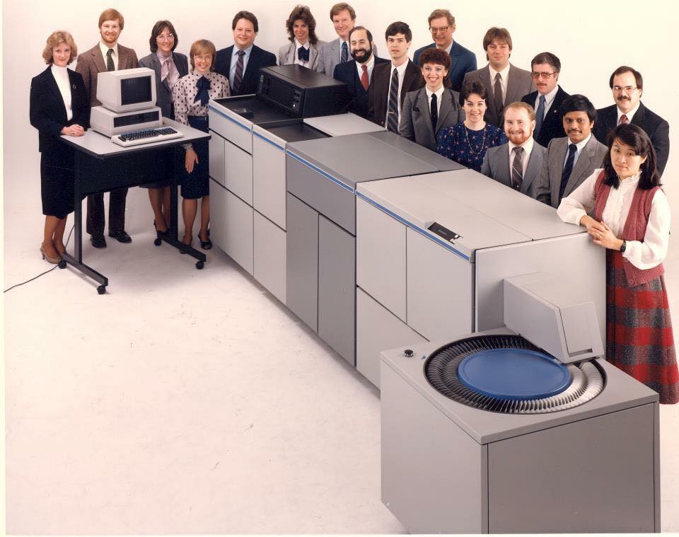
There was a time when Kodak was not just a company, but a true home. Within its walls, thousands of people found not only a job, but a way of life. Careers blossomed there, lifelong friendships were forged, and dreams were shared that seemed as enduring as the light captured by its cameras. The workplace was filled with pride and a deep sense of belonging, where every individual achievement was celebrated as a collective triumph.
Kodak was a school, a refuge, and a source of personal success for entire generations. Many built their lives under the shelter of the company, trusting that the strength of that giant would always be there. But a story once written in golden tones took an unexpected turn. The lack of innovation, the inability to adapt to new times and the digital revolution, led to a dramatic downfall—one as harsh as it was unforeseen. No one ever imagined that such a symbol of stability could vanish so suddenly.
The loss of thousands of jobs was not only an economic blow but also an intimate, almost familial pain. Today, what remains is the memory of a luminous era and the nostalgia of all that was lived and built. There lingers also a small wound, a quiet but constant sorrow, for the ungrateful ending of a story that marked our lives.
Kodak may no longer shine as it once did, but in the memory of its former employees, the pride still glows—pride in having been part of a great family, in having contributed to a legacy that, despite its ending, continues to live on in every memory and in every photograph once developed with hope.
Here is a very interesting Youtube video about the rise and fall of Kodak:
KODAK: How Could the Industry Pioneer Fall so DEEP?
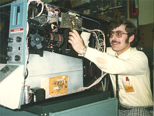
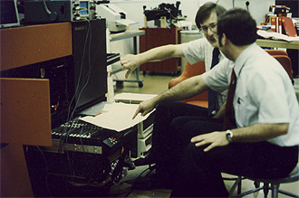
Rick Swenton in 1974, with pocket protector, installing a zoom kit in a
Kodak Microstar PR-1 Reader-Printer
From 1974 through 1997 I worked for Eastman Kodak Company based in Rochester, NY. I worked in the Office Imaging division as a Field Engineer, Field Specialist and later as a Service Manager out of the Connecticut office. I was not involved with consumer products like cameras or projectors but I had the great pleasure of installing and supporting some of the most sophisticated electronic, mechanical, optical, medical and chemical devices in the industry. These included microfilm systems, document scan-store-print systems, mainframe computer connected laser writer film printers, high speed printing and publishing, OCR Scanners, professional photofinishing systems, radiography systems and even blood analyzers.
This page is a work in process gallery of equipment that I and my friends supported at Kodak. I begin with the models I worked on starting with the oldest models that probably were introduced in the late 1940s and early 50s.
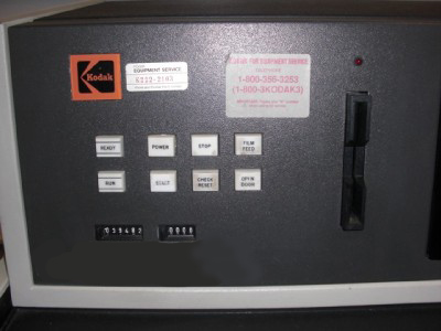
The K-Number!
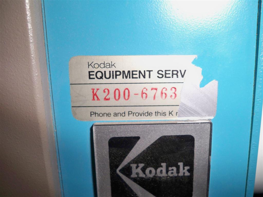
Some time in the 1980s Kodak decided to computerize it's field service operation. This involved having the Field Engineers (originally called Equipment Service Representatives or ESRs) place a unique identifier number on each piece of Kodak equipment. This number was on a durable sticker and was called the "K-Number." (What else?) We had to physically travel to each and every machine to install these numbers while verifying the equipment serial number, customer contact name and phone number. After this was done, if you were a customer and called Kodak for service, we told YOU who YOU were! Kodak first created the software system called Scan-1 to process service calls. It was a client-server application that ran on IBM System-34 computers located at all of the local district service offices. Later, Scan Plus was released and the computers were upgraded to System-38. Nightly backups were saved on 8" Floppy Disks that were in a library pack. The service reporting system was a client-server called STAR (Service Tracking and Reporting.) It ran on Sun Microsystem client computers also located in the district offices with the host and backup host in Rochester NY. These were originally linked to the home office with 9600 baud dial-up modems.
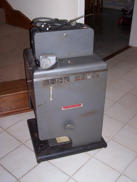
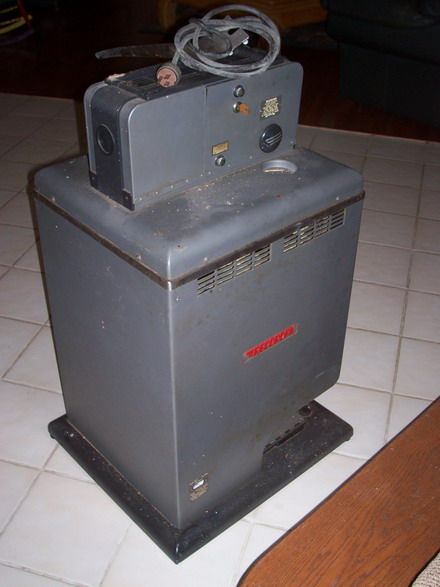
Recordak
Recordak was a subsidiary of Eastman Kodak Company that manufactured microfilm equipment. It was created in 1927 after purchasing the rights to manufacture a machine that photographed bank checks. It was invented by George Lewis McCarthy, who called it the Checkograph and was issued his patent on 25 Feb 1930 (No. 1,748,489). The New York Public Library began using microfilm to record the New York Times for the library archive.
Kodak used the Recordak name for a long time and later continued to produce microfilm equipment under the Kodak name.
Rotary Microfilmers
Microfilmers are document cameras usually used by companies to photograph documents for archival purposes and then discard the huge amounts of paper that would have to be otherwise stored. A rotary microfilmer is not like a still camera. There are no frames on the film. The document is imaged while the document AND the film are in motion! That means the film consumption is directly proportional to the length of the document. Some microfilmers had a manual document feed system. The operator inserted one document at a time into the microfilmer. Since this was very time consuming an automatic feeder was developed. The typical automatic document feed system (called a feeder) consists of a softer feed roller turning inward to pull the top document in and a harder separating roller turning backward to push the bottom documents out, so only one document at a time was pulled in ... until the rollers wore out! Conveyor belts move the documents to the aperture - two long narrow glass plates (called glass flats). The document passes between the two glass flats which hold the document flat and precisely position it for imaging. A front and rear lamp bank illuminate both sides of the document. A series of 45 degree mirrors reflect the light from both sides of the document to the film unit. Both the front and back sides of the document are photographed side-by-side on the film. Inside the film unit is a roll of 16mm film, a take-up spool (empty reel) and a film drive roller. The film drive roller is a precisely manufactured rubber coated roller that both drives the film forward and provides a flat plane for the projection of the document image to be placed on the film. As the document is being sped through the microfilmer by the conveyor belts the image of both sides of the document is being projected onto the moving film at the film drive roller. If you select a reduction ratio of 48x then the film is moving 1/48 as fast as the document. The amount of film used is directly proportional to the document's length and the optical reduction ratio. Remember there are no frames on the film in a rotary microfilmer. A bank check uses less film than a letter document. Trip Fingers under the glass flats operate a switch to tell the film unit to start moving the film and open the shutter to allow the light in as soon as the document enters the aperature. You can imagine the problems one can have if the document and film do not stay exactly synchronized. If the film slows down with respect to the document, the photographed image will be compressed (called contractions). If the document slows down, the image will be stretched (called strecthes). If the film speeds up, the document will be stretched.
How can the film motion speed up or slow down with relation to the document? Microfilm does not have sprocket holes like movie film. This was done to keep company employees from taking microfilm home to try in their movie cameras. With no sprocket holes to keep the film synchronized to the mechanics, they relied on the rubber film drive roller to maintain positive contact with the film. The film wrapped around the roller for almost 300 degrees and had tension. That didn't stop problems. When the rubber became glazed it could slip and the film could slow down. This would cause contractions of the images Also, the take-up reel had to have some tension to wind up the exposed film. If that tension was set too high it could pull the film so hard that it would slip on the film drive roller and advance too fast. This would cause stretches of the images.
Let's not forget about document jams. You are feeding more than 500 documents a minute. They have to be individually separated at the feeder, be transported to and make it through the glass flats, then be transported out of the machine and stacked in the exit tray without jamming. The documents were usually well-handled, curled, dog-eared and torn. They build up static electricity when the went through the microfilmer. There were brushes that tried to neutralize the document static. Sometimes the operators would complain about getting multiple static shocks from the machine!
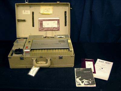
Bantam Microfilmer
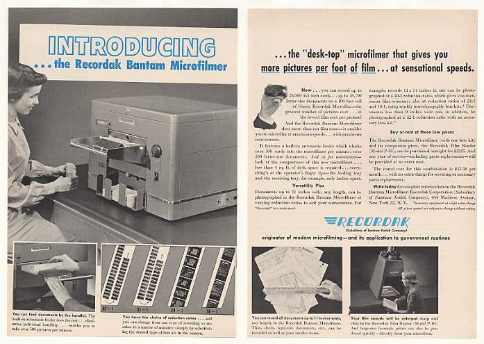
The Bantam Microfilmer was one of the earliest models. During the 1970s we would occassionally find one of these in the back room of a rural branch bank. This one has a manual feeder so the checks had to be inserted individually by hand.
Model RH and Model RL
I worked on a few of these in my time. They were very old, perhaps manufactured in the late 1940s.
Model RM and Model RM-1
The models RM and RM-1 were typically found in many branch banks in the 1970s to film checks before leaving the bank for processing. They were older models when I supported them and were probably hand-me-downs from the bank's main offices. These models were all metal with heavy cast assemblies. The electronics consisted of relays, resistor-capacitor time delays and big solenoids. It filmed both sides of the document in one pass. They had an automatic document feeder, models FRM and FRM-1. The ergonomics of this microfilmer were right out of World War II. It looked and weighed like a battleship.
Microfilmers often had a mechanical document counter that was advanced each time a document was photographed. It looked like an old car odometer. I once had a regional bank who used their RM Microfilmer to count money! Remember I spoke of the inconsistent reliability of the automatic document feeders. When misadjusted or when the rollers wore out there could be document overlaps and even jams. When I reminded the operator who was counting the money about the potential for a mis-count she told me she simply counted the stack of bills twice. If the second count matched the first, she trusted the count!
NH and NH-1 Endorsers
These microfilmers frequently had endorsers. Endorsers were mechanical accessories that had a rotary rubber stamp pad with the bank's name, ID numbers, and the word PAID. As checks passed through the microfilmer, one side of the check would get stamped by the endorser. For the RM, the NH endorser used wet ink (usually red). A system of rollers would transfer the ink to the rubber stamp. Working on endorsers was a real pain because of the ink. The red ink was indelible. It was impossible to clean it off your hands or clothes. One time I dropped the rubber stamp onto my white shirt. It rolled down the whole front of my shirt repeatedly printing PAID and blobbing ink all over me. As I left the bank, one of the tellers joked that it looked like I was in quite a bloody battle and asked me who won!
These endorsers were all mechanical. They used a sensitive trip finger assembly that moved a pawl into a toothed wheel to provide mechanica power to release the clutch that would turn the rubber stamp (called a die). When the ratchet wheel became worn, the pawl would not engage all the time and the checks would get hammered into the trip fingers. This would cause missed stamps, nicking of the leading edge of the check and often cause jams.
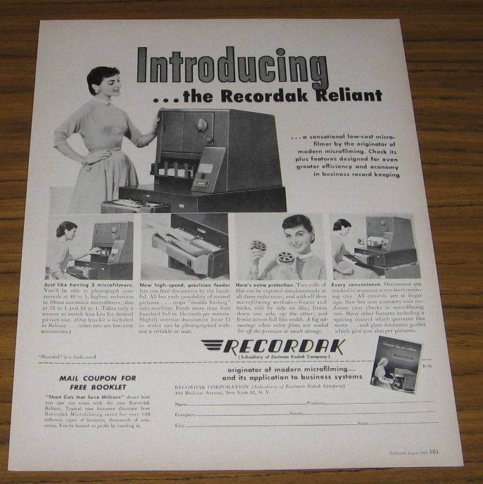
Reliant 500 Model RS
Index Lines
The Reliant 500 Microfilmer introduced an indexing feature called the Kodamatic Indexer. This was a series of small lamps positioned just above the aperture and so slightly into the camera field. A bank of switches on the front panel would turn these lamps on or off. The lamps would cause a fine line to be imaged on the film inbetween and behind the document images. Depending on which lamp you turned on, the line of the film would change position. When you were searching for documents on film later, and advancing the film in the reader at high speed, the line is easily visible. If you recorded the position of the line while you were filming the documents you could use that information to help you locate an approximate position of specific documents on the film. There were stick-on charts for the reader that had the line position which corresponded to the settings that were used during filming.
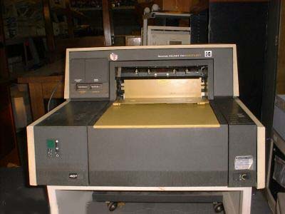
Reliant 600 Model RW and Reliant 600 Model RW-1
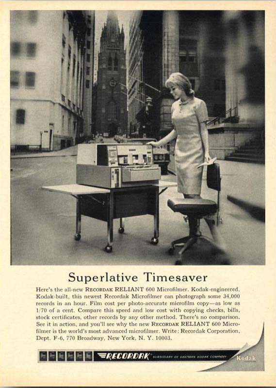
In the 1960s and into the 70s the RW and RW-1 was the mainstream microfilmer. It was the same size as its predecessor, the RS, but it had a more modern look. It didn't look like a military device from the war but had beige colors and a nice matching stand. The RW continued to be a mostly all-metal product. Starting with the RW, Kodak introduced Automatic Exposure Control, an external box that connected to the exposure lamp banks and a sensor to adjust the brightness of the lamps for the different color documents. The Automatic Exposure Control for the Reliant 600 was called the AEW.
Sequential Imprinter
The Sequential Imprinter made its debut with the Reliant 600. The NSI stamped an eleven digit sequential number on each document while it was in motion! The NSI used eleven mechanical font wheels (called modules) that were advanced by a solenoid ratchet within each module. The Imprinter had an eleven digit wide typewriter style ink ribbon. A huge solenoid operated rubber bar would press the document into the ribbon to make the imprint. Only the five least significant digits were sequenced. The 6 most significant digits were used for batch information such as the Julian date or department number. Starting with the Reliant 700 Microfilmer the Sequential Imprinter was simply called SI. The SI was basically the same NSI design with better electronics and repackaged to fit the Reliant 700. The digit modules were the same.
Image Marker
The 600 was the first microfilmer to provide image marks. At this time these were simply small square black marks at the edge of the film next to every document image. They were used to sequentially count documents on readers that had retrieval systems like the IC-5. Coupling image marks with a sequential imprint and recording how you indexed your documents you could easily retrieve specific images later by using a roll number, document number indexing system. This system of indexing was designed to work with the IC-5 system installed in a PR-1 reader and I think even a Lodestar, perhaps the PS-1K with the IC-4 system. Later on, Kodak introduced a computer assisted retrieval system called KAR. Computer software was coupled to the retrieval process. To search for a document the computer told the operator what roll of film to insert into the reader. Then the computer sent the sequence number to the reader. The reader counted the index marks to reach the desired document and the document appeared on the screen.
The RW-1 and FRW-1
The FRW-1 Document Feeder marked the beginning of the new style feed and separating rollers. Until this time feed and separating rollers contacted each other as they turned in opposite directions. The two feed rollers were pressed into the two separating rollers and they eventually wore out because of both the documents that passed through and the friction from each other at the contact point. The FRW-1 feeder used feed rollers and separating rollers that did not make contact. The separating rollers were offset so they merged into the empty space between the feed rollers. They did not touch the feed rollers directly like the old system. This resulted in better separation, less wear, and no need to turn off the rollers when the machine was idle.
Reliant 400 Model RO and Reliant 400 Model RO-1
These were economy microfilmers that came out around the same time as the 600. They were slower. They used the same removable film unit as the Portable RP shown below. Like the RP, the 400 used a complex mechanical system of cams and clutches to coordinate moving film, opening the shutter, closing the shutter and stopping the film, in that order. If the shutter opened before the film started moving, you would get black bands on the leading edge of the image. If the film stopped moving before the shutter closed you would get black bands on the trailing edge of the image. If the shutter opened too late or closed too early you would get image cut-off. This was all adjusted by moving split cams!
Here is a Portable Microfilmer RP-1 sitting on it's carrying case.
With the 700, Kodak stopped the two letter model designation. The 700 used more plastic parts like covers and housings. The electronics were brought into the modern age with more integrated circuits. The 700 feeders continued to use the new design feed and separating rollers. The 700 feeder used 4 feed rollers and 5 separating rollers but the separating rollers were aligned to press into the space between the feed rollers and not to touch them directly. This resulted in better separation, less wear, and no need to turn off the rollers when the machine was idle. A later design of the feeder provided for offset feed rollers. When using Image Markers the right side of the document path was reserved for the image mark on the film, so documents positioned there would be cut off by the image mark. With the feed rollers in the center of the feeder it was problematic to feed checks off to the right side. The offset feeder moved the feed rollers to the right so they would be in the center of the offset document path. An accessory Automatic Exposure Control was no longer an external box but was built into the 700.
700/750 Sequential Imprinter
This was an improvement over the 600 NSI with better electronics, better document sensing (photocell and lamp), easier maintenance. The digit modules were the same as the 600. They were mechanical wheels with numerals 0 through 9. They were rotated mechanically with a ratchet/pawl mechanism operated by a solenoid. The digit wheels had a zero reset switch and a transfer switch. The transfer switch operated when the wheel transitioned from 9 to 0 and provided a pulse to advance the next module in the decade. For example, when the units module passed from 9 to 0 the transfer switch in the units module would provide a pulse to increment the tens module.
The zero reset switch would open when a module was at zero. This was used to send a stream of advance pulses to all the modules to reset them to zero. The pulses were sent through the zero reset switch. When the module reached zero the switch would open and no more pulses would reach the module.
Endorser
The 700 Endorser marked the end of the complex mechanical endorser. Finally somebody got brilliantly smart. The 700 Endorser was elegant and simple. The rubber stamp (the die) consisted of three sections of curved dies that comprised 360 degrees of the die drum. The old endorsers had a trip finger/clutch assembly to rotate the die and make one "Paid" imprint per check. With the new 700 Endorser, the die drum was always turning. The characters that needed to be imprinted on each document, such as "Paid" and the date (manually set by date wheels in the die drum) were repeated three times in one revolution because there were three dies in the drum. This meant that short documents like checks would get stamped "Paid" and the date at least once but possibly more than once. But who cares as long as it got one complete stamp. Long letter size documents would receive a continuous long stripe of printing with the words, numbers and dates repeating over the length of the document. Because the ink coated die was always turning, the designers had to figure out a way to keep the ink from transferring to the document transport rollers in the machine when no documents were going through. They designed the die to only have printing in rows with gaps between the rows. Then they designed the discharge roller (the roller that would press the bottom of the document into the die for printing) to have gaps in the rubber that aligned with the printing on the die. Remember the die drum and discharge roller were always turning. This meant that when no documents were passing through the machine, the ink coated die letters and numbers would be rotating through the gaps in the discharge roller, so no ink would be transferred to the discharge roller and no ink would contaminate the machine or documents.
Electronic Image Marker - EIM
This was an add on circuit board that introduced the first microprocessor to Kodak microfilmers. It was available for the 750. It used an Intel 8748 8-Bit CPU. In conjunction with the Sequential Imprinter that had the optional EIM document sensor installed, the EIM could perform more sophisticated automatic indexing of the film. It provided three different image mark sizes, usually referred to as Book-Chapter-Page indexing. Previously there was only one size image mark. The EIM also had a patch reader. The patch was a special document pre-printed with a bar code pattern at the leading edge. When preparing the documents for filming, the preparers would manually insert a patch document in the stack of documents where they wanted to change batches. The EIM would recognize the patch and automatically change the image mark size. This system of indexing was designed to work with the IMT series of Reader-Printers and also with the KAR Computer Assisted Retrieval system.
Reliant 450 and Reliant 550
These were economy versions of the 750. The 450 did not have a removable film unit. It also did not have automatic exposure control. However, the 450 and 550 were the first microfilmers to use florescent lamp banks. Previously all microfilmers used eleven automotive style bayonet socket incandescent lamps (like a single filament brake light). Because florescent lamps decrease their brightness with age more than incandescent bulbs, the 450 and 550 did have a lamp monitoring system that increased the lamp voltage as the lamp got weaker. The 450 was also different in that it only had 4 document conveyor belts instead of the customary 5. This resulted in the 450 having considerably more document jams than other machines. I can't remember how many belts the 400 had.
The 450 built in film unit had a pull cord to manually advance the film when loading, unloading or putting a space between batches. The operation of the pull cord looked like starting a lawn mower. Many times we could not resist making a wise crack when people gave us a strange look while we were pulling the cord. We said, "Don't worry. It's just flooded. It will start in a minute."
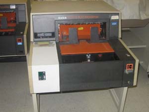
Reliant 800
The Reliant 800 was very similar to the 700/750. The external appearance was updated and it had a few new features but it was basically the same machine.
Reliant 800 Sequential Imprinter
The 800 Sequential Imprinter was also similar to the 700/750 with improved document sensing. This provided a more reliable operation of the 800 Intelligent Image Marker (EIM) system.
The 2000 sported multiple complex circuit boards with several microprocessors (a few 8085s and 8049s and more). This microfilmer was like the 800 on steroids.
ImageLink-70
I don't have a lot of first-hand experience with the ImageLink series of microfilmers. By this time I was a Service Manager and my team was supporting these models.
ImageLink-30
ImageLink-990D Scanner
I also never personally supported Kodak Scanners.
Scanner 900
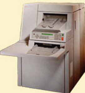
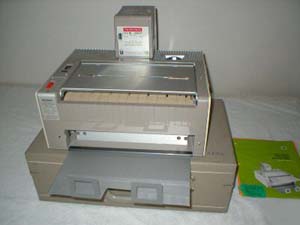
Desktop 3 Microfilmer
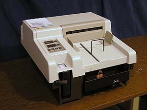
The Desktop 3 microfilmer was frequently found in banks, usually behind the teller windows. It was an economical replacement for the aging RP-1 portable microfilmer.
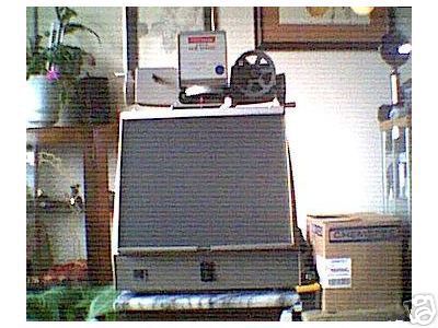
Rotoline Microfilmer
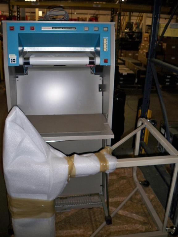
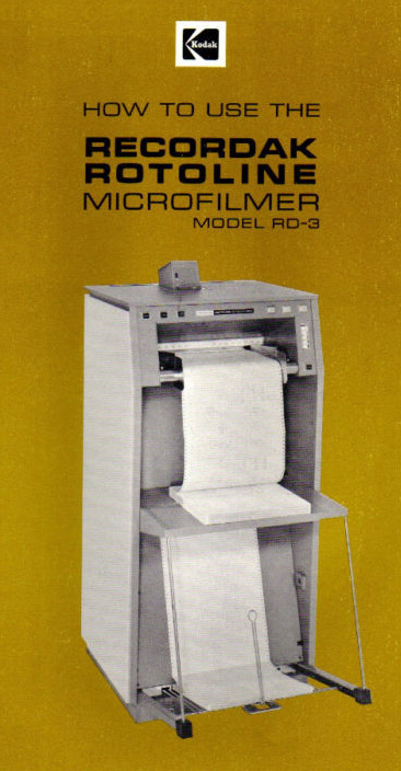
The Rotoline was a rotary microfilmer that filmed continuous form computer paper. Remember when mainframe computers spewed out giant stacks of fan-folded paper? The Rotoline was able to photograph those stacks of form-feed paper on to microfilm. This microfilmer transported the fan-fold paper at high speed. It was a paper jam waiting to happen. Can you think STATIC!
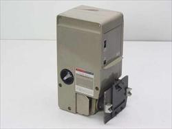
Here's a picture of the CD-2 Film Unit that went with this model.
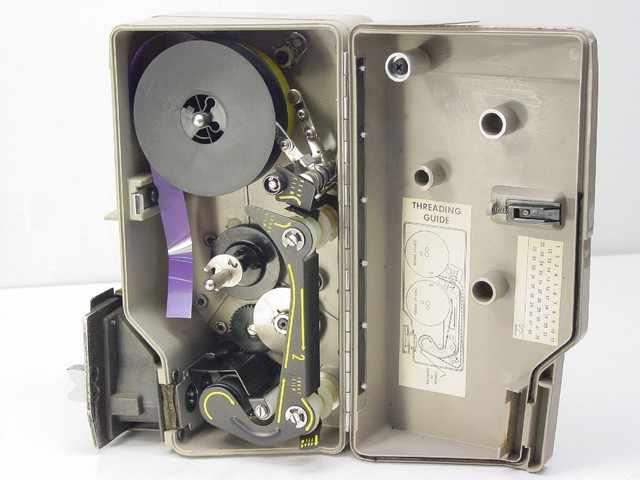
Here's the inside view of the CD-32 film unit. This film unit design was used on the Rotoline RD-2, the Portable RP and RP-1, and the Reliant 400 Microfilmers. The only difference was the interface and mounting mechanics.
Planetary Microfilmers
Planetary microfilmers differed from rotary microfilmers in that the document remains stationary when being imaged and there are frames on the film, although the frames size can be variable depending on the model. Planetary microfilmers are strictly manual feed so they are slow to use.
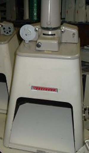
Models JA, JC and JD
This is a Junior JC-1
These photos were submitted to me by Jeff Cogburn who was a BSMD/BIS Sales Manager in Houston. Thanks Jeff!
This is a Recordak Junior Microfilmer JD. The document is placed on the white platen through the front bottom. The left and right exposure buttons need to be pressed at the same time. This ensures the operator's hands won't be in the picture! We did have a quite humorous service call on a planetary microfilmer. There were complaints of a foreign object repeatedly appearing near the bottom area of the image. The foreign object was obscuring the important information on the document. After a thorough investigation we delicately informed the operator that the foreign object would no longer appear if she sat further away from the front of the microfilmer!
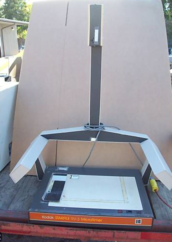
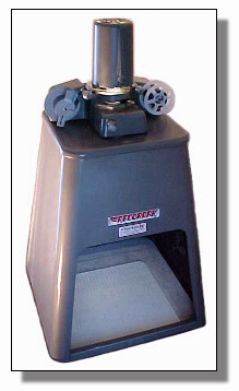
RV-1 and RV-2
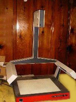
This is the RV-2
These were small tabletop planetary microfilmers. The RV-1 was very small and had a check size tray in the front. The RV-2 was bigger with a document size table and two fluorescent lamps on the side arms. With a planetary microfilmer, the document does not move when photographed. It remains stationary, flat on the table, and the camera takes the picture just like a regular consumer camera. In this case, the film is "framed." That means you consume the same amount of film to photograph a bank check as you do photographing a letter. There were two florescent exposure lamps in the "arms" and an button on the base to press for exposure. I can't tell you how many hands were photographed when people tried to work fast and didn't get their hands out of the picture in time.
MRD-2 and MRG
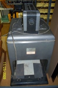
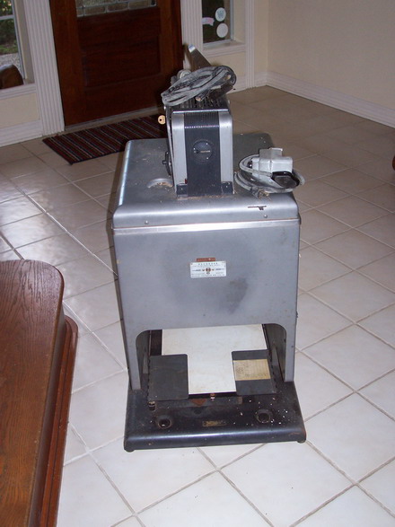
These microfilmers were big! They consisted of a large flat table with the film unit on a tall overhead tower and exposure lamps on overhead arms. The document was placed flat on the table. The reduction was adjusted by cranking the film unit up or down on the tower. There was a small projection lamp inside the film unit with a target slide to project the target on the document so you could see how big the imaging area was before you took the picture. The MRG was the big boy. This one had great resolution and was used frequently by customers who had to photograph at a very high resolution or meet military specifications in their document archiving processes.
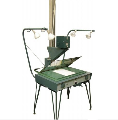
The MRD-2 was one of the larger planetary microfilmers. The Film Unit (camera) was on the column in the middle and could be cranked up or down to change the reduction. A projection lamp in the Film Unit would project a rectangular image on the platen (the desktop surface) so you could see the area of the platen that would be in the photograph. Exposure control was accomplished with an autotransformer controlling the four flood lights.

MCD-2 Film Unit
Microfilm Readers and Reader/Printers


I actually worked on one of these Kodagraph Model C Readers in 1974 in an insurance company in Hartford. Even at that time, Kodak did not stock every part for this model. In those days businesses squeezed every ounce of life out of their old equipment. They could do this because Kodak always tried to help.
MPE-1 Reader
This was the reader of the day for many libraries. It was around for a long time because libraries did not have money to spend and the MPE still did the job for decades. The MPE accepted 16 or 35mm roll film. It was the most basic machine with a projection lamp, glass flats and a white screen at the bottom of the machine. It simply projected the document image down from the top and on to the screen inside the base. The "head" rotated almost 360 degrees to display images that were oriented differently on the film. The film was advanced with a crank on the right side. Mechanical connection of the crank to the head was accomplished with a flexible cable (like a speedometer cable) so the head could rotate while still connected to the crank.
Lodestar PS, Lodestar PS-1
The Lodestar PS and PS-1 were the first cartridge loaded readers. This made them very popular in places like Motor Vehicle Departments for things like searching registrations and titles. The film transport was accomplished by several motors controlled by 2050 gas-filled (xenon) thyratron tubes! This wasefore SCRs were available. The motor speed was controlled by a speed control lever that operated a complex series of leaf switches that tried to accomplish smooth staging of film transport speed. Since this was not a closed-loop system the speed was usually erratic as mechanical wear and tear created friction with the moving parts.
Lodestar PEK Reader-Printer
The PEK was a Lodestar with a printer. The printer used silver photographic paper and was developed with a monobath solution. Now picture this: The printer was installed on the top of the Lodestar. The Lodestar electronics was in the base. The corrosive and conductive. monobath solution was pumped up to the printer and into the developer tray. The paper was passed through the monobath in the tray and dried with squeege rollers much like an old-fashioned ringer washing machine. When the printer developed a monobath leak the solution traveled downhill into the electronics in the base. Many a Lodestar went up in smoke after a leak!
PV, PVA and PVM
Reliant PVA Reader (hand crank, no motors!)
The PV, PVA and PVM were very small desktop readers. The PV and PVA had a hand crank to advance the film. The PVM was motorized. Speed control for the PVM was a rheostat for slow speed and staged leaf switches on a control lever for medium and high speed control. The PV series never had a printer accessory. The film was loaded in the rotatable head of the reader and passed between a pair of glass flats to keep the film in focus. The small motor in the PVM got pretty hot and burned out motor brushes frequently. After a period of years the motor would become full of carbon brush dust and it would smoke when it got hot.
PE-1A
This was a reader/printer that had a rotatable head like the PV and PS / PS-1. The printer used regular photographic paper and used a monobath chemical solution to develop the image like the PEK. Unlike the PEK, the chemistry was at the bottom of the machine so it could not leak on the electrical components. Actually, it never leaked unless the tray was cracked because it did not have a pump or hose. Film speed control was done with a mulit-stage leaf swicth and a rheostat. The PE-1A had the same style motor as the PVM, so motor brush replacements were common along with overheated motors.
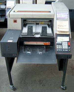
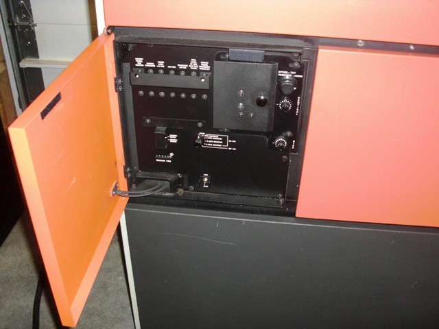
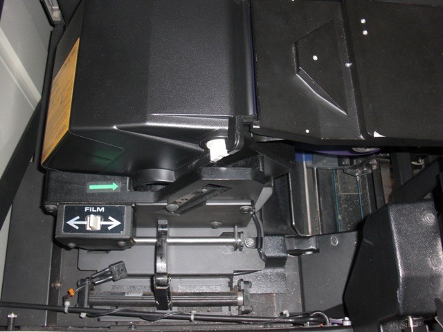
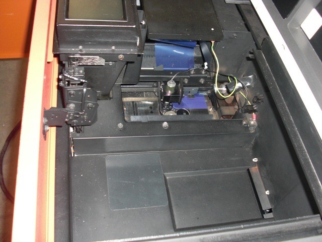
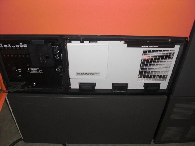
MPG/ERG and PR-1/ERG
This is the Kodak Motormatic Reader model MPG. It was a manually-loaded system with a variable speed film advance controled by the speed/direction control lever on the right. The focus control dial is on the left. In the center, below the screen, is the dial to rotate the image on the screen. The MPG could be attached to a B-Base which looked like a desk cabinet. The B-Base would house the ERG printer to allow the MPG to make photocopies of the microfilm images on the screen. Glass Flats (plates of glass) kept the film flat and in focus. The flats opened when the film was being advanced in high speed to keep the flats from scratching and wearing the film.
The ERG was an electrostatic kerosene-based liquid toner printer. The printer had a tank that held the liquid toner with an electric pump to pump the toner into the processing tray that the paper passed through. Leaks were commonplace along with contamination of customer floors. The copy paper was on a roll and cut to size by a knife. A tubular high heat lamp was used to dry the paper before exit. In case of a paper jam, the heat lamp promptly burned the paper causing a smell that customers frequently described as dead fish. The ERG had several PC Boards in a card cage using transistors and an array of reed relays.
The PR-1 Reader accepted a film magazine with a special leader like the Lodestar. This reader had no take-up reel. The film simply dropped by gravity into a plenum chamber where the film "accumulated." From the point where the leader was pulled from the cartridge, it had to make it from there down a film track, past the aperture, and down into the plenum on its own without jamming. The leader was much thicker and more durable than the film. The PR-1 used a transistor based motor control system with a DC motor that had a generator output for feedback to achieve a smooth film scanning.
IC-4 and IC-5
The IC-4 was based on the older PEK reader/printer.
The IC-5 was based on the PR1/ERG reader printer.
These readers searched sequential images on a role of film by counting image marks - small timing marks next to each document. Typically the search was done in high speed. The film was moving so fast that the system would shoot right past the desired document, recognize that it did, slow down and stop, go into medium speed reverse, overshoot the desired document again, stop and change back to slow speed forward, and finally stop on the desired document.
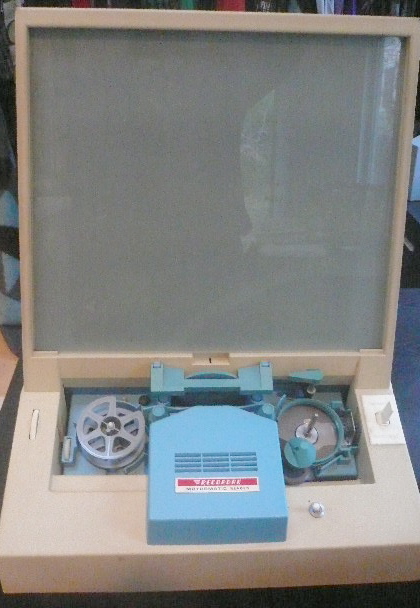
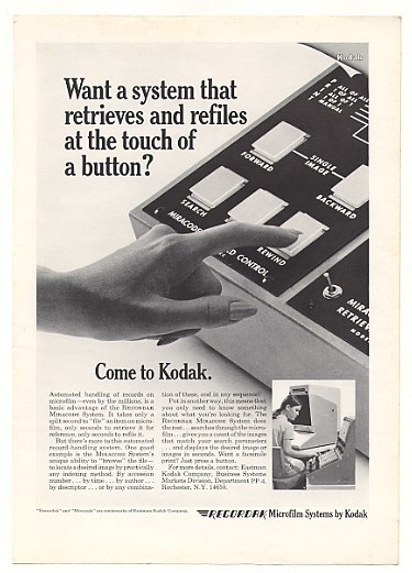
Miracode
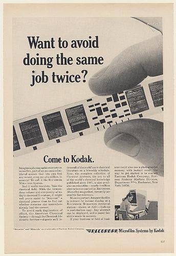
Miracode is the registered name that stands for "Microfilm Information Retrieval Access Code." The basic unit of this automated, high speed, retrieval system is the Recordak magazine which contains a 100 foot roll of 16 mm microfilm. The system includes a control console, a microfilm access file and a Recordak Lodestar Reader-Printer or a Recordak Microstar PR1/ERG Reader-Printer. The Miracode System is capable of making a highly sophisticated search by user defined descriptors such as client name, account number or any other category.
The original Miracode system was based on the older PEK reader/printer.
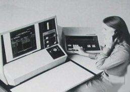
Oracle Microimage Terminal
The Oracle Microimage Terminal was the successor to Miracode. It was based on the Starvue Reader/Printer frame. Other than the nameplates the only way to tell an Oracle from an IMT was to look at the keyboards. Oracle exposures were also made on a planetary microfilmer, like the RV-2. Unlike Miracode, the Oracle code was not placed in the subsequent frame on the film. Instead, the oracle barcode was recorded along the edge of the film, next to the document, in the area where IC-4 and IC-5 image marks would be found. This saved on film usage. The Oracle Microimage Terminal was designed at a time that was between discrete component circuits and microprocessor options. The electronics were good but it was not computer controlled.
IMT-100, IMT-150, IMT-250
The IMT-100 was based on the Starvue (below) but had no printer. The IMT-150 and 250 looked like the Starvue with a printer. All had calculator style keyboards and displays to enter the information to perform a search on film. The IMT-100/150 was based on the Intel 8085 microprocessor and had around 12K program memory in 2K EPROMs! The IMT-250 had a more powerful computer with more search features. The film transport system had a sophisticated closed-loop servo control system that was able to precisely control film motion without looping or jamming. The IMT used a shaft encoder to send timing pulses to the computer so the software always knew what was going on with the film motion. Because the IMT had closed-loop feedback for film movement the scanning was very smooth. Built-in service diagnostics were very good. We could energize any load and read any sensor.
IMT-300
The IMT-350 was totally redesigned. The Ektamate Printer was replaced with a Minolta plain paper printer engine in the base. No more expensive thermal photographic paper.
Kodak KAR Systems
An offshoot of the IMT line of products was the Kodak KAR systems (Computer Assisted Retrieval). One example was the KAR-4000. It was equipped with an Applied Digital Data Systems ADDS-Mentor 4000 minicomputer. The computer used the Pick operarting system and was programmed for information retrieval. Using the computer software to search your records it would tell you which roll of microfilm your desired documents were on. Once the film was inserted into the IMT reader the computer would send the sequence number of the document on film and the IMT would go to it. Besides the ADDS minicomputers, other KAR systems used minicomputers from Prime. The KAR-7500 system used a Digital Equipment Corp. Microvax II minicomputer.
Kodak KIMS Systems
The Kodak Information Management System was an automated microfilm retriever. From an office upstairs, a user could specify a specific microfilm cartridge stored below in a basement. A robotic arm would fetch the microfilm and insert it into a scanner. The resulting electronic image was then delivered to the requestor’s workstation. This was a very expensive system costing around $450,000 in 1985.
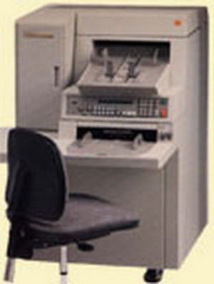
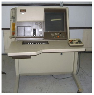
Starvue Reader-Printer
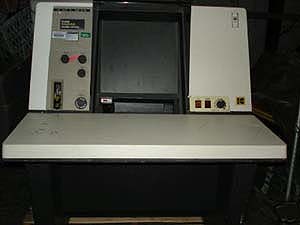
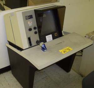
On the left is a Kodak Starvue Reader Printer. On the right is a Starvue without the printer. Notice the empty space on the right side.
The Starvue was the first reader to offer the new style film feed system with the reel drive and thread drive belts instead of feed roller and pressure roller on the PR-1. The Starvue also dispensed with the plenum chamber and returned to the take-up reel. There was a film drive roller under the glass flats to provide smooth film scanning. The control board finally consisted of modern electronics using totem-pole and bridge power transistor configurations with motor-generator tachometer feedback. The Starvue had three motors for moving film. It had a supply motor used to pull the film back onto the supply reel. It had a take-up motor used to pull the film up into the take-up reel. When one motor was pulling the other applied a small amount of reverse pull to keep the film from looping. The Starvue also had a capstan motor which was used for slow speed scanning. This film drive system not a closed loop system. The slow speed film scan was controlled only by the slow speed capstan motor. The supply and take-up motors only provided film tension during scanning. In the later IMT series Readers the capstan motor was eliminated and a computer control closed-loop system was used to scan the film at all speeds. The computer used a precision shaft encoder to determine film speed and direction.
The Starvue had an optional Ektamate Printer. This was a very nice printer. It used no toner or chemicals. The paper was expensive silver-based photographic paper but it was processed with only heat. The paper was on a roll in a light-tight box. Because the paper was photographic paper it was sensitive to light. The paper was fed out of the box inside the darkened reader, cut, and positioned for imaging. After the Starvue projected its image on the paper for a timed exposure, the paper was fed into the processing drum. This drum was about 4 inches in diameter. It had an aluminum core and was coated with a white high temperature cloth-like pad. The drum was surrounded with heated, polished aluminum plates that actually contacted the drum surface. Using only friction, the paper was fed into the rotating drum where it was pressed into the drum pad by the curved heater plates. When the paper came out, it had a nicely readable image of the document on the film. This printer had a lot of plastic parts. It really sounded cheap when it ran, making clicks and clacks and boing sounds. But it actually ran better than anything previously manufactured.
The temperature of the heater shoes needed to be accurately controlled or the image quality on the copy would vary. There were thermistors inside the heater shoes. Those signals were fed to an analog temperature controller which operated two triacs. The controller IC sensed AC line zero crossings to switch the triacs on when the AC line voltage was zero. This reduced electromagnetic interference and reduced stress on the electrical components.
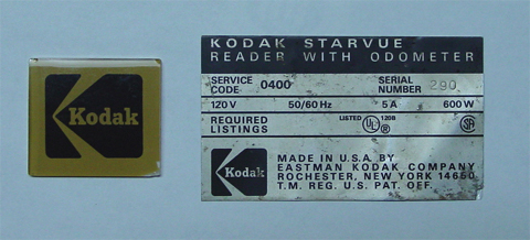
Mrs. Janet Fuller sent me these items above: The Kodak Logo and the serial number plate are from a Starvue Reader. She is an owner of an antiques/collectible business. While on a walk in Ft. Pierce, Florida she found a demolished Starvue in a makeshift dump. Very little of it was intact but she managed to retrieve these from the carcas. Thank you Janet for saving these and sending to me. Opening your letter was like opening a time capsule!
Ektalite Reader
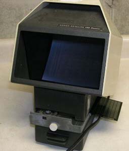
The Extalite reader was a very economical microfiche reader. It was not very rugged being mostly made of plastic.
FRF-1600 Jacket Loader Reader

This interesting device was used to make microfiche from strips of 16mm film. The strips were inserted into a "jacket" with channels to hold the strips. The jacket was the size of 105mm microfiche. The jacket was placed on the shiny platform on the right. The roll of 16mm film was placed on the spindle on the left. The platform moved from front to back. You positioned the platform to accept the first strip of film. Then you advanced the film into the first channel on the jacket. The film was cut to length. Finally you moved the platform to the second channel to accept the next strip of film. You repeated until the jacket was full.
Normally you did not use the jacket to view the film. The jacket was much thicker that microfiche. When placed into most fiche viewers the jacket usually caused focus problems. The glass flats in the reader could not be held flat because of the increased thickness of the jacket. It was common to make a copy of the jacket using a fiche duplicator. The copy process was either Diazo (Ultraviolet light and ammonia) or Vesicular (Ultraviolet light and heat.)
Intelligent Digital Workstation IDW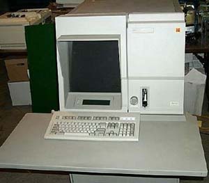
The IDW was released after my time as a Field Engineer. I don't have any experience servicing it. By that time I was a Service Manager. This workstation had an internal IBM PC or clone.
Ekatfiche Duplicator
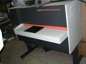
The Ektafiche Duplicator was often seen as a companion to a Komstar. This was a vesicular microfiche duplicator. The original microfiche was manually placed on the platen glass and the platen was inserted into the duplicator. The number of copies desired was set with a thumbwheel switch. When you pressed Start, a rubber platen came down to press the vesicular copy film flat against the master fiche on the platen glass. The shutter opened and a very strong ultraviolet light projected the master fiche image on to the copy film. After the proper timed exposure the platens seperated and the copy film advanced 148mm and cut with a rotary knife blade. The film was then heated to a high temperature by being pressed between two rotating developer belts. This heating process developed the visible image on the copy film.
This machine had a few challenges. The ultraviolet lamp was powerful, required very high voltage, and ran hot. The lamp originally had some design problems and frequently exploded before reaching the end of its projected life. The exhaust fan would pull the hot pieces of shattered glass out of the machine and drop them on to the customer's carpet where they would promptly melt into the fabric. The developer assembly consisted of a pair of heater blocks each surrounded by high temperature rubber conveyor belts. The original design experienced frequent wear of the belts and roller bushings. It was common to hear the shafts and bushings squeaking away and the belts tracking off to one side. A new developer assembly was released that was vastly improved.
The Ektafiche Duplicator was not designed and built by Kodak. It was only marketed under the Kodak name. I got into a bit of trouble advocating for my customers who were complaining about lamp explosions. I wasn't getting any answers from Kodak Service Engineering probably because the original manufacturer was not cooperating. I discovered that Sylvania manufactured the lamp and it had a part number. I decided to call Sylvania directly to ask why the lamp was exploding. I was transfered from person to person. Each person was more nervous than the previous one. When I finally got to the top I was told by the Sylvania person that this particular UV lamp was specifically made for Kodak and I would have to talk to a certain person at the Kodak Apparatus Division. Not stopping here, I called the engineer at KAD. I told him I was calling about the exploding lamps. The first words out of his mouth were, "WHERE DID YOU GET MY NUMBER?" I responded, "Sylvania." After he finished choking I got the chapter and verse which I will paraphrase and is not an exact quote. He was really angry! "How dare you bypass Kodak Engineering and go directly to one of our vendors. You are a mere Field Engineer and have no authority to do this." Now I am mad. I told him, "I had to do this because I am my customer's advocate. I tried to get them help through my normal contacts at Kodak Service with no success. It seems if I don't move to the next step then nobody will. Feel free to complain about me to my management and I will feel free to mention that you have been an obstacle to Kodak Customer Satisfaction. You and I can be friends. Or not." A few weeks later, Kodak announced the availability of an improved UV exposure lamp. This one had reinforced porcelan coated ends where the lamp was bursting. After that, the lamps no longer exploded and I did not lose my job!
404A Diazo Fiche Duplicator (companion 404C not shown)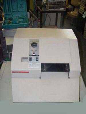
This is another (much older) fiche duplicator. It used diazo film. The exposure process was similar to the Ektafiche Duplicator above. It used ultraviolet light to image the master fiche onto the copy film. This was done in the 404A.
The companion 404C was the machine that developed the copy film. You took the undeveloped copy fiche from the 404A and inserted it into the receptacle on the 404C. When you pressed the button the receptacle would close to create an air-tight chamber for which to inject ammonia gas! This gas came from a pressurized canister inside the 404C. The canister looked like a miniature version of a tank for welding torches. After exposure the gas would be bubbled through water to produce household ammonia which would be discarded down the drain.
You can imagine the field day OHSA woud have with this machine today! If the plates on the receptacle were not perfectly parallel when they came together the ammonia gas would leak out. There were many days we came to service these machines and the office had been evacuated! The gear drive system that moved the plates together was a little noisy and grindy. The sound of a malfunctioning 404C was unmistakable. You pressed the button and you heard: "Grrr, rrr, rrr (gear noise), (motor stop), then "SHHHHHHHHHHHHH" (ammonia gas leaking), then Grrr, rrr, rrr (gear noise).
Oh the interesting days we had in the field!
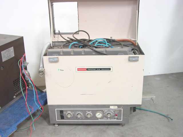
Prostar and Prostar-II Processor
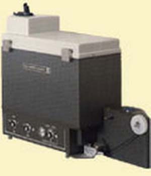
Recordak Prostar Model DVR
The Prostar-II and the older Prostar DVR were very similar processors. They developed black and white 35mm and 16mm microfilm. Inside the Prostar were five stainless steel containers called tanks. Six racks of rollers were inserted into the tanks. The first double-sized Tank was filled with developer solution for Racks 1 and 2. The next Tank was filled with water for Rack 3 to wash off the developer. The next 2 Tanks for Racks 4 and 5 were filled with fixer solution. Finally the last Tank for Rack 6 was filled with water to wash off the fixer.
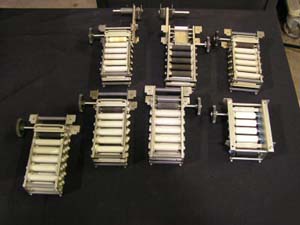
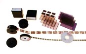
Set of Prostar racks.
These racks were inserted into the tanks. The Racks were installed in this order: Developer, Developer, Water, Fixer, Fixer, Water. The last rack was for hot air drying. The six tanks were immersed in a larger hot water tank.
Timeout for a funny story. Margaret and Maureen worked in the microfilm department of the local office of a regional bank for many years. They must have processed tens of thousands of rolls of microfilm. One day they placed a service call on their Prostar processor for blank film. Before going to their office, I called them on the phone. It was highly likely they accidentally switched the locations for the developer and fixer chemicals. When you do that, you get blank film. I asked them to check that the chemicals were not swapped. They were insulted that I implied they were capable of this basic mistake. So I get in my car and travel to the bank. When I arrive, they give me the stink-eye. I go to the processor, stick my finger into each chemical tank, one at a time, and smell each of the contents. Then I carefully announce to the ladies, "There's fixer in the developer tanks and developer in the fixer tanks." I wish I had a camera to capture their facial expressions and a recorder to record their conversations. "Maureen! I though YOU checked the chemicals!" "Margaret! I thought YOU checked them." They became my friends for life when I told them I wasn't going to charge them for the service call. Now they don't have to explain to their manager why they caused an unexpected bill because of their mistake.
Precise temperature control was mandatory or the density of the developed film would vary. The incoming water temperature was controlled by a thermostatic mixing valve. This was a large wall-mounted control with a thermometer display and a control knob. It blended hot and cold water and constantly adjusted the blend to keep the water at 96 degrees F. Inside the processor main water tank there was an immersed temperature controlled heater and circulator to keep the water moving and the temperature constant. As fresh hot water was pumped in, the old water was released into the overflow pipe and sent down the drain.
With fresh chemicals the Prostar could process up to 3,000 feet of 16mm microfilm. Then the chemicals had to be replaced. Kodak made an external chemical replenisher. This was a device where you could install a jug of developer and a jug of fixer and the replenisher would feed in new chemicals based on your usage. With the replenisher you could process 18,000 feet of microfilm. I was going to say 18,000 feet before running out of chemicals but I don't think it was that simple. I believe after that you had to disassemble the Prostar, do a thorough washing, and replace the developer and fixer in the tanks with fresh chemicals to start over.
As a by-product of film developing some amount of silver was discharged into the waste water. Besides silver being expensive it was not environmentally friendly to dump it down the drain. Kodak sold a silver recovery kit to reclaim some of the silver. The drain water was piped into a large canister the size of a 5 gallon pail. After the water passed through the canister it was sent to the drain. I am not sure how much this canister cost and the charges for recovering the silver from it. At one time all of the larger companies embraced this process. Later, silver recovery seemed to go out of fashon. Perhaps the cost to recover the silver was more than the value of the silver recovered.
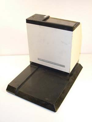
Kodak Xomat ID Camera
This camera was used to photograph text data on to x-ray film. The film was contained in a flat light-proof holder. The top right corner of the holder was inserted into the bottom of the camera. A printed card the size of an IBM punch card was inserted into the top of the camera. When the exposure button was pressed, the camera would open a trap door on the x-ray holder, reflect an image of the text that was on the card and expose it on the x-ray film, and then close the door on the film holder.
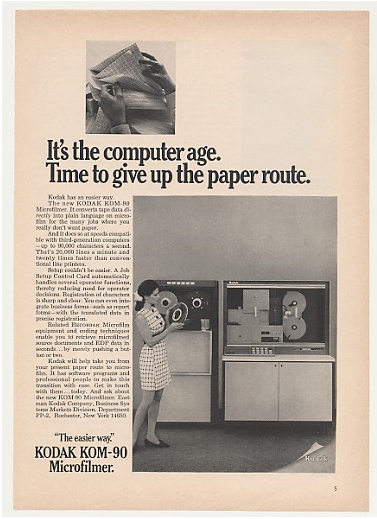
This is an ad for an Kodak KOM-90 Computer Output Microfilmer with a TT-90 Tape Drive.
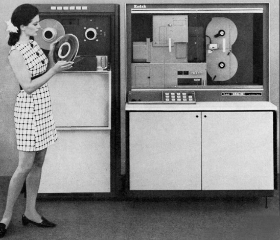
Here is a larger photo from the KOM-90 ad.

The KOM-80 was Kodak's first computer output microfilmer. The Kodak KOM series of Microfilmers and accessories were manufactured for Kodak by other companies. The KOM was a microfilmer that allowed for computer data to be directly imaged to microfilm instead of being printed on paper. The KOM 80, 85 and 90 were connected to 1/2 inch tape drives that read the computer data tapes and exposed 16mm film or 105mm film that was cut to microfiche length. The first tape drive was the TT90. I have never seen one of these. The second tape drive was the MTU made for Kodak by Hewlett Packard. The TT90 used the NRZI format (Non-Return to Zero). The electronics in the TT90 were incredibly difficult and time consuming to adjust. I believe the TT90 could also be retrofitted with the more modern PE format (Phase Encoding) like the MTU. This format was a breeze to service, especially in the MTU. Because of parity error correction you could even pull one of the nine amplifier boards while the MTU was reading tape and the system would keep on going just fine.

Some of the KOM systems were connected to an HP minicomputer and HP tape drive which was used to convert tapes from IBM, Burroughs, Univac and other mainframe systems into the KOM native format.
The KOM-80, 85 and 90 used a very bright CRT to project the image onto the film. The form image (the printed background on fan-fold computer paper) was etched on a glass slide and flashed onto the film with a xenon flash tube. The data on the CRT was not written like a TV picture with scanning lines like a video raster. In order to achieve the crispest character quality, each letter and number was "stroked" like a human would write a character with a pen. Here's how it worked:
The CRT had two sets of deflection coils - main deflection and character deflection. The main deflection moved the electron beam to the coordinates of the first character of the first line. Then character deflection moved the electron beam around to write the character in much the same way you would write it with pen strokes. It was not as easy as it sounds. It takes time for the electrons to travel from the CRT cathode to the phosphor coating on the screen. If the intensity of the beam was not controlled precisely, uneven character density would be noticed on the film. So the electronics had to coordinate the turn on and turn off of the electron beam in conjunction with main and character deflection. As main deflection advanced to the character position, the electron beam was turned on slightly ahead of time so that the beam arrived at the destination at the same time main deflection was finished. By the same token, the beam needs to be turned off slightly before character deflection finished its stroke so that the beam stream stopped ay the same time the stroke was finished. The whole process is like writing script with paint from a garden hose nozzle and creating consistent character thickness and darkness!
If you think this is challenging, the screen surface of the CRT was flat to keep the image in focus on the flat film. The electron beam in a CRT when moved with the magnetic deflection system moves in an arc. This creates distortion on a flat screen. The electron beam is shorter when hitting dead center of the screen than when hitting anywhere near the outside perimeter. This causes what is known as Pincushion Error. A square image projected on a flat screen would have curved sides. To correct for this, electronic pincushion correction was applied to tweak the deflection amplifiers to compensate for the curves. All this was done with analog circuitry. It was complex and had many adjustments. The field engineer was constantly looking through the viewer (the bore scope) to adjust for image variations and running film tests to confirm quality and get customer sign-off.
The alpha-numeric characters and symbols were stored in a diode matrix. Each caracter had its own printed circuit board. The system used a binary counter to drive the rows and columns on the diode matrix board. This means the diodes were not arranged on the board in a human-readable format. If one diode was bad it could render the whole character unrecognizable. Remember, the characters were not generated in a dot matrix. They were "stroked" as if they were written by a pen.
The camera device was either 16mm roll film or 105mm roll film that was later cut to microfiche. For the 16mm camera, the film was advanced one frame, the form slide was flashed, the CRT image was projected, and then the camera moved the film to the next frame to start over again. For 105mm fiche, the process was more complex. Microfiche is organized in a row/column format in two dimensions, unlike roll film which is a single column, one document wide. So a fiche camera needs to move the film in two dimensions, starting in Row A, making images in Columns 1 to 10, then going back to Column 1 but dropping down to Row B and so on. Now we get into the challenges of precisely moving and stopping a high speed two dimensional platen that is moving the film. The system used stepper motors with encoder wheel feedback. Analog circuits were used to provide delays for settling times so that the mechanics have enough time to dampen their motion before the film is exposed. Otherwise the film will be wiggling during exposure and the image will be blurred. If the settling time was set too long the machine would actually slow down and impact throughput. If it was set too fast, it would negatively impact image quality.
Over a period of time the mechanical parts in the camera would wear out and require a longer settling period to dampen out oscillations after positioning the platen. As you increased the settling delay the customer would notice the machine slow down. The only way to get the speed back along with a good image was to overhaul the camera and replace all the pulleys, bearings and cables. Any mechanical "play" in this system would cause optical distortion of the document on film.
The microfiche camera was called the Versaform Camera. It had its own logic bin with around 10 printed circuit boards using RTL, TTL and analog integrated circuits.
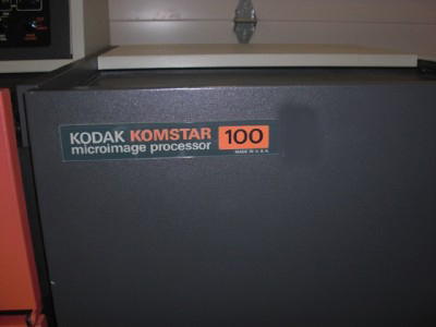
Komstar and MIP-IV - Computer Output Microfilmers
 |
The Kodak Komstar was a computer output microfilmer that emulated an IBM 1403 or 3211 mainframe attached line printer. They were installed in the data center and connected to an IBM mainframe computer with bus and tag cables. In Hartford we also were able to get a Komstar running on a Univac system at the Gas Company in the 1980s. The Komstar could also operate in a stand-alone mode connected to a half-inch tape drive. |
The Komstar used a helium-neon laser to write characters on the film. It did this with a highly complex electro-mechanical system. The main laser beam was passed through an acousto-optic modulator. This was a block of glass with quartz plates that was fed with nine discrete radio frequencies in the 40-50 MHz range. Each of the nine frequencies corresponded to nine incidental beams of laser light that exited the modulator at nine discrete angles. Each beam corresponded to nine dots (or pixels) of a 7 x 9 dot alpha numeric character. This was essentially an electronic emulation of a dot matrix line printer. As the minicomputer processed the incoming data from the mainframe it would turn on or off the nine radio frequencies which would turn on or off the dots of laser light that would write characters on the film.
Just as in a dot matrix printer the print head would have to be moving to write a line of data, the Komstar had a line scanner. This was a small mirror attached to a galvanometric motor that would move the nine beams of laser light from left to right to write a line of characters as the dots were gated on and off. The galvanometric motor is like a regular motor but the shaft is bound to the motor body. The shaft is flexible in the rotational direction and is not allowed to rotate. It can only twist slightly, left or right of its center rest position, much like a zero-center meter movement.
Dot matrix line printers had a timing signal for the print head to provide servo control of the motion of the head. Without closed-loop control, if the print head scan speed increased or decreased because of mechanical binds the characters on the page would be stretched or compressed. In the Komstar the timing signal was generated by reflecting a light source off the back side of the line scanner mirror and sending it through a reticle bar - a clear plastic bar with black timing marks. A sensor monitored the reflected light as it was interrupted by the bars and generated the timing signal to keep the generation of the dots synchronized with the position of the line scanner. The reticle bar system is similar to a timing fence found in dot matrix printers.
So as the line scanner scans a line of characters there is another galvanometric motor and mirror called the page scanner that will move the laser beams down the page to the next lines. The page scanner did not have a closed-loop servo. It did not move as fast or as much as the line scanner. But when it was used, the heat it generated caused it's mirror position to drift. That caused the page image on the film to drift. To compensate for this, there was an electric heater with closed loop temperature control to keep the page scanner motor as hot when idle as it got when running.
If all this is not complex enough, now we need to make rows and columns of page images on microfiche coming out of a continuous roll of film. We need to accurately move the film through the rows and columns while positioning it on top of the lens, holding it down flat against the lens with a solenoid operated platen during exposure of each page, and then cutting the film exactly 148mm long.
The film used in the Komstar was a thermal film that was developed with a dry process using only heat. The cut fiche was passed to a heat drum. The fiche was pressed against the drum for about half of its rotation by a high temperature tolerant cloth conveyor belt. The fiche exited the Komstar as a finished product.
The Komstar only wrote characters on the film. To make the pages look like images of continuous form computer paper the Komstar used an image of a blank piece of continuous form paper with an outline of the page and horizontal lines. The image was placed on a piece of glass called the form slide. A bright light would project through the glass and on to the film. A shutter would control exposure time. Using a test pattern on a view screen the Komstar operator would have to align the position of the form slide against the laser generated lines of characters to make sure the characters were centered between the lines on the slide. This process is very similar to aligning continuous form paper in a printer so that the printed lines fall within the color bars on the paper.
After a few years the laser would get weak and need replacement. As you would guess the process was not easy. The new laser beam needed to be in the exact same position as the old one. We used a process called Retroreflection. Using a special fixture and mirrors we would complete a complex, detailed and systematic process of reflecting the laser beam back on itself to ensure accurate positioning.
Later on we learned a way to substantially reduce the time to replace a laser and not have to perform retroreflection. If you darkened the room lights, defeated the cabinet safety interlocks, and removed the view screen and the lens, the Komstar could project its laser light on to the ceiling. If you marked the place the laser dot hit the ceiling before you changed the laser and you adjusted the new laser to make its light hit the same spot, you were close enough to not have to go through the lengthy retroreflection process. Of course this quicker procedure violated every government safety regulation with the laser beam exiting the product. The laser was only 5mw so the only real danger was looking directly into the main beam. The beam projected on the ceiling was one of the nine beams from the AO modulator so the power was substantially less than the 5mw zero-order beam. We were still careful.
My time supporting Komstar products at Kodak was perhaps the most rewarding period of my career. The technology was complex and challenging. Working in the computer rooms of large corporations and dealing with CIOs and IT managers honed my skills and paved my way into management. It was also rewarding to be able to help my peers when they were stuck on tough problems.
 Here are some photos of my Komstar 200/300 Training class in 1978.
|
|
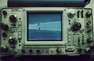 An oscilloscope display of the analog reticle signal (top) and the first character signal (bottom). The reticle signal is created by reflecting a light from the back of the line scanner mirror and through a reticle bar. The reticle is a series of black and clear bars with a wider one positioned shortly after the beginning. The wider bar indicates the point where the first character was to begin the line of written text. |
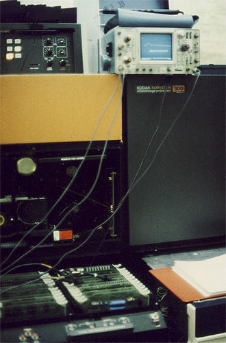
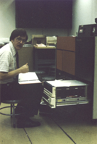 Paul Sultan troubleshoots the Data General Nova 3/12 Mini-Computer. In these days we were provided with programs we hand-toggled into the Nova front panel to help diagnose problems. We also carried a tape reader in our cars. The cassette tapes held comprehensive diagnostic programs that were essential to servicing the Komstar. |
 The Logic Bin pulled out. We were required to troubleshoot the Komstar down to the component level. Most times we took the boards out of the computer room to solder components. We didn't want the smoke from the solder to trip the customer's fire suppression system. Besides the costly fee for recharging the Halon, tripping the smoke sensors would power down all the customer's computer systems. |
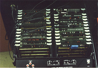 As you can see there were 20+ boards depending on the configuration. Six of the boards in the front on the right side are the IBM Channel Interface. They provided Bus and Tag signals to plug directly into an IBM channel on a mainframe computer. |
 Instructors Junior Lee and Dave Zobel. If you came late to class they required you to buy doughnuts. On the second day of class I arrived early with doughnuts for the whole class. The instructors said that was required only if you came late. I told them I wanted to build up credits so I can come late any time I wanted. |
|
|
|
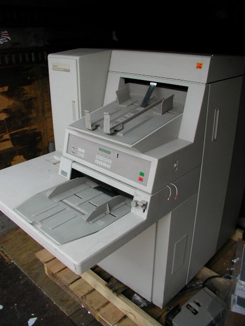
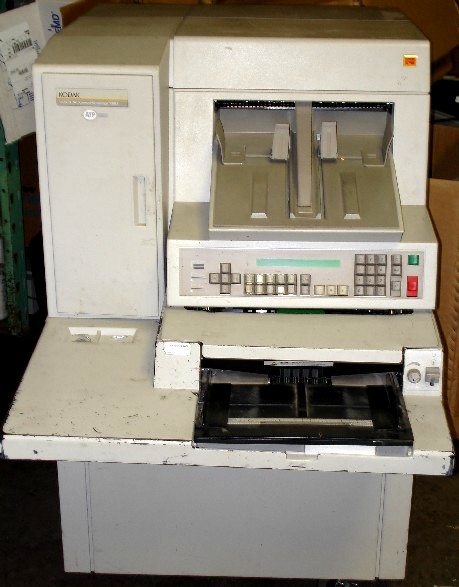
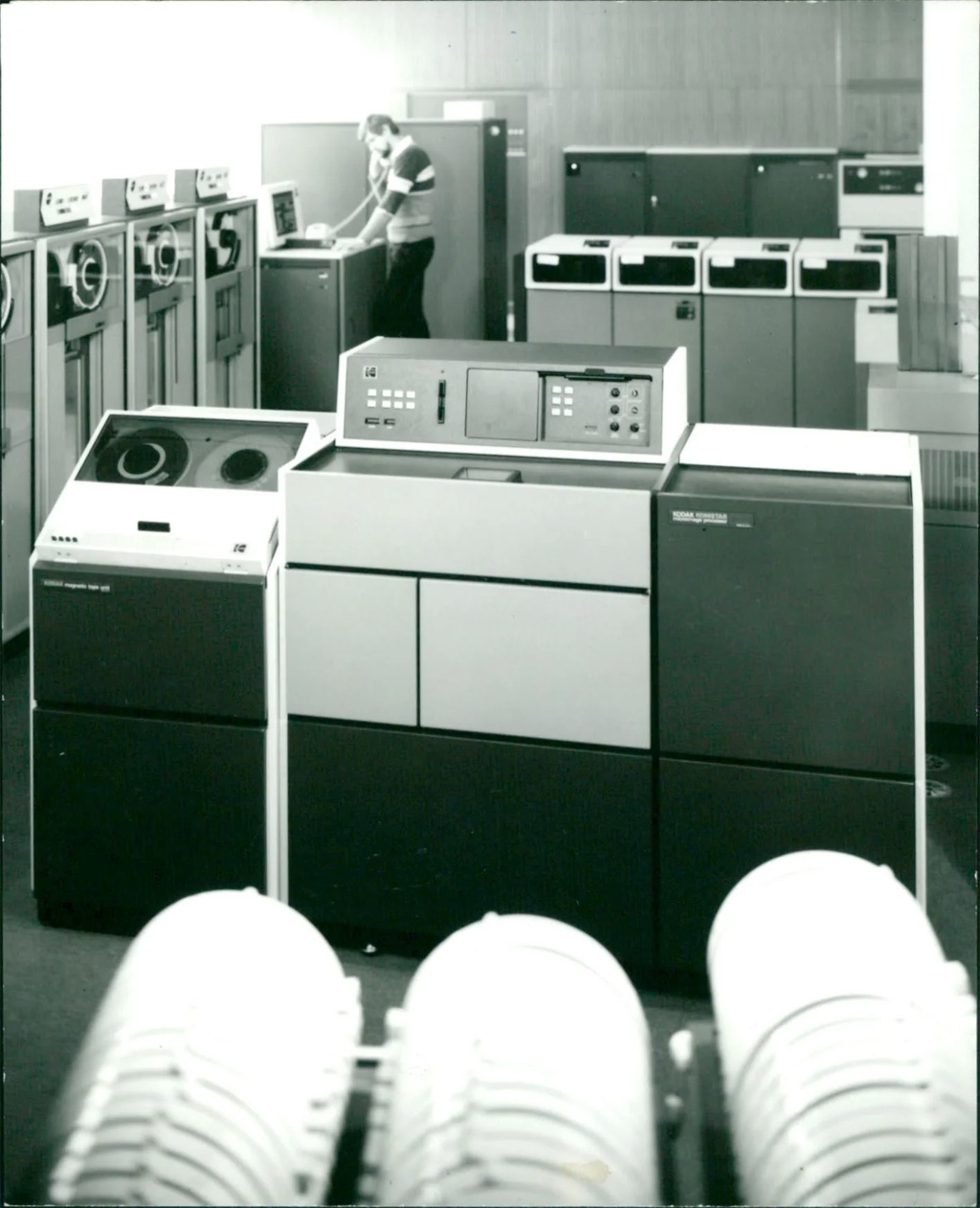
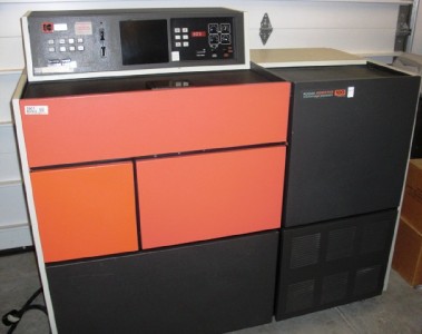
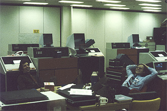
 The following pictures are various views of a Komstar 100. The 100 was dedicated to tape drive input. The 200 was mainframe attached (bus and tag cables.) The 300 was switchable between tape and mainframe. |
|
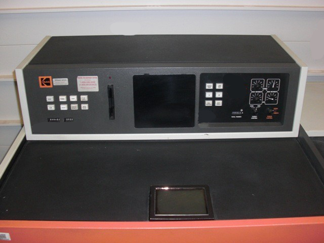 Top view showing the whole control panel and the view screen. |
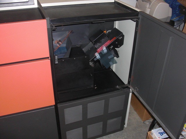 Right side showing the film processor (developer.) Minicomputer is behind the louvered panel. |
 Front control panel with power breakers, form slide, and form slide adjustment controls. |
 Film Canister and film feed mechanism. |
 X-Y Carriage and film platen (stomper.) |
 Another front view with left panel removed. |
Kodak MIP-IV Microimage Processor and Finisher-IV
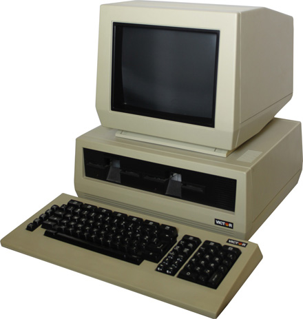 I don't have any photos of these products. The MIP-IV was the next generation Komstar. The MIP-IV and Optistar had a Victor 9000 PC clone that was based on the Intel 8088 processor. This was used as a kind of job control terminal.
The Finisher-IV was the next generation Ektafiche Duplicator. The Finisher-IV was made by Photomatrix, an existing manufacturer of fiche dupicators. Kodak marketed it under the Kodak name.
Kodak Optistar
There is nothing found on the internet about the last iteration of Kodak Komstar products. The photo below is from the Kodak Komstar Alumni group on Facebook.
Kodak Ektachem Blood Analyzers
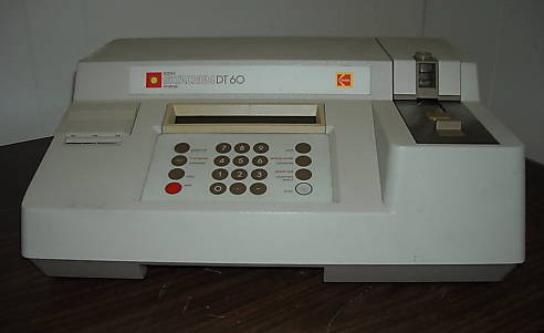
Yep, we serviced blood analyzers too. I often helped field engineers repair this model even though I never went for training. Other models were very large laboratory grade analyzers found in hospitals and testing labs. This smaller unit, the DT60, was often found in veterinary clinics. Instead of messy chemicals, a drop of blood was placed on a cardboard slide with a special coated layered material. The blood causes a chemical reaction with the materials in the slide which causes a color change based on the contents of the blood. A laser light is used to perform the photometric and colorimetric testing.
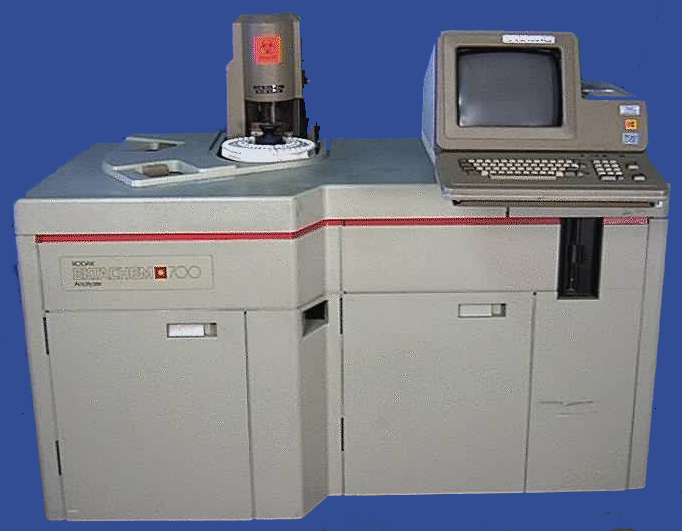
Here is the Kodak Ektachem 700 Blood Analyzer. It would be found in high volume testing facilities such as hospitals and labs.
Kodak Copiers
In 1975 Kodak entered the photocopier market with the Ektaprint 100. It's interesting to note that Kodak was rather late to the copier business compared to Rochester town rival, Xerox. But when Kodak copiers were introduced, their copy quality consistently exceeded that of Xerox products. This was because Kodak designed and manufactured its own organic photoreceptor (originally called a "film belt) as well as its own toner and developer. Older copier designs used a selenium drum as the photoreceptor. In 1975, Kodak copier information was considered company confidential because of market competition. All of the service manuals at that time were marked confidential.
It is interesting to note that Kodak's first copier to market, the Ektaprint 100, was one of Kodak's first products to use a microporcessor. In this case, the chip was an Intel 8008. This chip was about as powerful as a four function calculator. However, the copiers operational functions were done with a computer program. This means that bug fixes and enhancements could be made by updating the software (called firmware.) In this case, the firmware was contained on ROM chips. Updates involved replacing the ROM ICs. I think these ROM chips were 2K and there were 8 sockets. That meant the program had to fit in 16k of memory! There might have only been 256 bytes of RAM memory.
Another enhancement enabled by the microprocessor was called the Service Module. This was a black box that plugged into the top of the copier. The box contained a set of ROM chips that held service and diagnostic routines that helped the Kodak Field Engineer service and troubleshoot the copier. With the Service Module one could exersize individual devices like motors and solenoids or read the status of sensors. There were pre-programmed diagnostic routines to assist performing adjustments or test subsystems. For example, Program 402 would operate the main drive motor and pulse the flash lamps. Program 404 would read the toner concentration. Program 405 would read the condition of the Toner Exhaust Detector. More about toner blow-outs later!
The Service Module was not available to the public and was not for sale. This made servicing Kodak Copiers by third-party service organizations very difficult.
Regarding the photoreceptor, it was originally called a Film Belt. It was a consumable supply item that was stocked by the customer along with their toner and developer. Because the box was labeled "Film Belt" they were frequently stolen by customer employees who thought it had something to do with camera photography. Kodak renamed the Film Belt to "Image Loop" in an attempt to minimize theft.
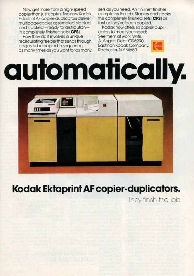
This is an ad for what looks like an Extaprint 150AF. The original Ektaprint 100 did not have a document feeder or a finisher (stapler, stacker). You had to place your original documents on the glass one at a time and collate/staple the copies manually. A document feeder was eventually released for the 100. The new machine was called the Ektaprint 100F followed by a finisher that would staple and offset stack the documents. That was called the Ektaprint 100AF. Later, the 150 was released which had a zoom lens. The 150 could copy the original document at 100%, 77% or 64% reduction. The original maximum paper size for all the 100/150 series was legal 8.5 x 14". The 150 had a larger glass platen and feeder so it could copy larger originals. Kodak coined the expression CFS which stood for "Completely Finished Sets." The copier did not use sorting bins for collation. With a copier with sorting bins, if you had a 10 page original and wanted 10 copies, the copier would make 10 copies of page 1 and drop each copy into the 10 bins. Then it would make 10 copies of page 2 and drop each copy into the 10 bins. When complete, you would have pages 1-10 in each of the 10 bins. The Kodak system would copy pages 1-10 in order, rotating them in the document feeder. The first copy of pages 1-10 would come out as a set, be optionally stapled, and dropped in the finisher tray. Then the copier would make another set of copies from the originals in the feeder. The second copy of pages 1-10 would come out, be optionally stapled, and dropped in the finisher tray but offset stacked from the first set. This would be helpful if the sets were not stapled because you would easily know how the sets were separated. The big disadvantage to this system is that the original documents were cycled through the document feeder ten times as opposed to only one time with a sorting bin system. This means the wear on those documents, and the chances for document jams, is significantly greater than the sorting bin system.
The 100/150 without the finisher was a large machine about the size of a washing machine and dryer side by side. Add the size of another dryer if you attach a finisher.
The 100 and 150 copied only in single-sided mode. You could make two-sided copies manually by putting the first side back into the paper supply and inverting the originals in the document feeder.
In 1976 I installed the first Ektaprint 100 copier to appear in Connecticut. It was at the Aetna insurance company in Hartford. It was serial number 23354.
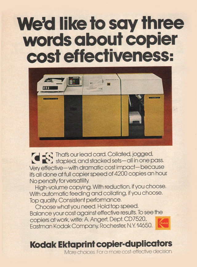
Here's another Ektaprint ad from 1976. It is impossible to find a photo of an Ektaprint 100 or 150 on the internet. Most of them are photos of the copiers made into promotional transistor radios.
A short time after the 100/150 was released, Kodak developed the Ektaprint 250 Duplicator which delivered two-sided copies in a single pass. Two-sided copying requires that toner be transferred to both sides of the paper. In order to do this in one pass the paper had to float on a cushion of air as it passed into the fuser and pressure rollers. Nothing could touch the paper on either side or the toner would get smudged. Other machines did two-sided copying in two passes, copying and fusing one side and then returning the paper back for an image and fusing on the other side. For a single copy of a set of originals, the machines that performed two sided copies in two passes would run twice as slow as the ones that copied two-sided in one pass. If more than one set was requested, the two-pass machine could achieve a fast speed. Should a paper jam or other problem interrupt the job there would be many sheets of paper that would be stopped in various locations within the copy process. All those sheets would have to be discarded and the originals would have to be placed in the document feeder in their original order for the job to be restarted.
Years later, improved models were introduced. Some models I remember are the 200, 220, 235 Copiers and the 300 Duplicator. The 200 series copiers did two-sided copying in two passes. The 250 and 300 duplicators did two-sided copying in a single pass.
Kodak 1392 Printer
Kodak also developed the Extaprint 1392 Printer. This was essentially an Extaprint 300 without a document feeder or platen glass. Instead, it had an LED print head that allowed computer generated documents to be imaged by the printer. Typically, the 1392 was connected to a controller such as an EFI Fiery Raster Image Processor. The controller converts the computer data to a bitmap that the printer can print. Usually the customer would send a Postscript file from their computer to the Fiery controller for printing. A common application would be Just-In-Time printing. For example, insurance companies would send you a copy of your invoice and a complete set of policy documents. The document set would be different for every client. Instead of printing the policy documents on a printing press and manually adding attachments, ammendments and invoices, the whole set would be printed on demand individually for each client. It would even include a cover sheet which had the client's name and address. The document set could be inserted into a mailing envelope with the address showing through a cellophane window.
Kodak KEEPS System
Kodak Ektaprint Electronic Publishing System (KEEPS) was an electronic publishing system. Using a minicomputer and the Kodak 1392 printer the user could create near-offset quality documents and brochures. The user could compose text, create graphics, preview layout and print a finished document.
Kodak Coloredge Copiers
Kodak also manufactured the Coloredge line of color copiers. The first Coloredge used three toner colors: magenta, cyan and yellow. The color black was hard to create because it needed perfectly equal amounts of the three colors. Later models added black toner. Some of the later models of Ektaprint copiers added accent color. These were not full-color copers but could provide black plus another color. The toner/developer station could be swapped to change the accent color.
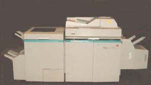
Image Source IS-70 Copier
In 1988, Kodak acquired IBM's copier business. It was estimated to include over 65,000 copiers. Kodak hired many of the existing IBM copier field engineers as well. The ImageSource IS70 was supposed to be the replacement/upgrade to the IBM Series-III copiers. Kodak was hoping that the IBM customers would migrate to the IS-70. The IS-70 development was plagued with problems and took seven years before it reached the market. It took so long that many former IBM customers with IBM copiers went elsewhere for replacements.
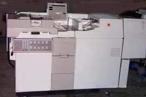
Imagesource 2085 Copier
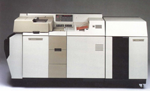 This is the Ektaprint 300 Duplicator. The main difference between this copier and the others is that the 300 performs inline two-sided copying. That means both the front side and back side of the paper is imaged in one pass. The process is quite complex. There is a point in the cycle where unfused toner is present on both sides of the paper. Nothing can touch the paper or the toner would smudge. The paper is floated on a cushion of air and sent to the fuser rollers. The earlier copiers would perform two sided copies by copying the first side and then sending the paper back to the beginning to copy the second side. With the 300 Duplicator, both sides are imaged at the same time, so the throughput speed is more than twice as fast.

Kodak QN Toner
All About Toner
Copier toner is a fine powder that has a consistency much like baking flour. Toner consists of plastic, carbon, and coloring agents. Toner is transferred to paper using an electrostatic charge and fused onto the paper with heat and pressure.
The plastic often consists of polyester or polypropylenes. The heat and pressure from the copier's fuser roller melts the plastic into the paper so it won't brush off. Carbon is used to create a black color. Other pigments can create color. Sometimes, minerals and other agents are added to imporve the ability of the toner to be attracted to the electrosatic charge. Toner is made into a fine powder. The smaller the toner particles, the greater the image resolution.
An interesting quality of toner is that while it is bascially inert it can be explosive. You may have heard about explosions in flour mills. The accumulation of the fine flour dust in an enclosed space can explode when triggered by an ingnition source. Toner has this ability. During the electrophotographic process in copers, the toner provided to the copies is not completely consumed. Some remains behind and is vacuumed away as waste. The vacuum filtering system has to use filters with a fine enough material to trap the toner and not let it escape from the copier. Kodak used a system called a Cyclone Seperator. This design is found in the Dyson vacuum cleaners. The air is sucked into the top of a conical chamber with the air entering at the wide part at the top. As the air swirls around in a vortex, the toner falls down through the narrowing cone and drops into a collection bottle. The air with most of the toner already removed is passed through a filter for safety and discharged into the room air.
You may ask how an explosion can happen. Toner is plastic particles. When you rub plastic together you build up static electricity. If you allow the waste collection bottle to fill up, the cyclone seperator will no longer work and toner will build up in the safety filter. When the safety filter reaches its capacity, it could breach and allow toner dust to be vented into the room. This was affectionatly called a "Toner Blow-Out!" The room will now have toner dust all over the furniture, shelves and into typewriter and computer keyboards. As this massive discharge of fine plastic particles is happening, the static electricity is rising so high that sparks can happen within the copier. A spark happening near fine toner dust can trigger an explosion. The vacuum system on Kodak copiers used flexible hoses with a metal spiral wire inside for strength. One of the first copier design updates was to ground the hose's metal spiral. That was the first place a spark would be generated from static build-up.
The explosion concern was so great that Kodak desgned a way for the service technician to vacuum the copier using the copier's own vacuum system. Ordinary vacuum cleaner filters were not good enough to capture the toner particles. They would just blow right through the vacuum cleaner and discharge into the room. Even more dangerous was that vacuum cleaners often used motors with commutator brushes. These produced sparks in normal operation.
For safety reasons, Kodak copiers had an airflow sensor that detected the proper operation of the toner vacuum motor as well as a toner dust sensor in the vacuum air exhaust chamber. Should the vacuum air stop or should toner dust be detected in the vacuum exhaust air, the copier would shut down.
There is an interesting story about this. The airflow sensor was a microswitch attached to a "sail" which was simply a small piece of thin cardboard. When the vacuum operated, the air pulled on the sail which operated the switch. The toner exhaust decetor was an LED light source shining on a photocell. When the photocell clouded with toner dust, the light would be blocked and the alarm would be triggered. Both of these devices were mounted in the vacuum air exhaust chamber. When a copier had a problem and was exhausting toner dust, the dust particles would contaminate the airflow switch before there was enough dust to cloud the toner exhaust sensor. The copier would halt with a false loss of vacuum alarm instead of the actual toner exhaust alarm. The contaminated microswitch was a better toner detector than the toner exhaust detector! This confused many a Field Engineer.
Speaking of interesting stories, the original Kodak toner and developer produced very nice photocopies. After about 100,000 copies a Periodic Maintenance was required. This involved replacing the image loop, developer, cleaning brush and emptying the toner waste bottle. The waste bottle was a tall plastic jug. The bottle was usually only about 20% full of waste toner between Periodic Maintenance servicing and emptied at that time.
Kodak copy quality was better that Xerox but near the end of the 100,000 copy service cycle, the quality was diminished. Customers were demanding better long-term quality especially requiring really dark, solid blacks. Kodak re-designed the toner and developer. This caused dramaticly dark blacks at the expense of a lesser fine gray resolution. The customers loved it. What was initially unknown was that the new toner and developer combination quintupled the amount of waste toner collected in the bottle. Formerly, after 100,000 copies, the waste bottle was only 20% full. Now, the bottle completely filled and many copiers began to have a toner blow-out before the Periodic Maintenance when the bottle would have been emptied. This caused the introduction of the toner exhaust detector.

Kodak K Developer
All About Developer
Developer consists of plastic coated fine iron particles. Developer almost looks like toner but because of the iron content it is very heavy and attracted to magnets. Developer is the carrier that brings the toner to the paper. Inside the developer station there is a roller with a long magnet inside. When deveoper contacts the roller the developer stands up on end much like when long hair stands up from a static charge. When you add some toner to the developer, the plastic toner particles rub with the plastic coated developer particles as the roller turns. This creates a static attraction between the two particles. Now the mixture of toner and developer is "standing up" like hairs on the surface of the roller as it turns. This creates a soft brush that can apply toner to the copier's photoreceptor. Here's how the process works:
- The photoreceptor is charged with a high voltage. (Primary Charger)
- A bright flash of light projects the original document image onto the photoreceptor.
- The bright light discharges some of the high voltage charge. Where there was printing on the original document (black areas) the charge will remain.
- The photoreceptor is rotated to the developer assembly. The magnetic roller brushes the toner/developer mixture onto the photoreceptor.
- The charged areas where the original document printing was located will attract the toner.
- Toner particles will leave the developer but the developer will remain in the developer assembly captured by the magnet.
- A sheet of paper is fed to meet the toner image on the photoreceptor.
- The paper is charged with a high voltage. The charge on the paper is stronger than the charge on the photoreceptor. The toner will leave the photoreceptor and jump to the paper.
- The paper is immediately sent to the fuser roller where heat and pressure will melt the toner into the paper before the toner can smudge off.
- The photoreceptor is discharged with a high voltage alternating current (Cleaning Charger) and rotated to a cleaning station where a bright lamp will neutralize any remaining charge and a brush and vacuum will remove the waste toner.
- The cycle repeats for the next copy.
Another interesting product we supported was the Kodak Picture Maker
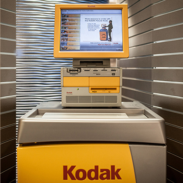
Found in drug stores, supermarkets and print centers, the Kodak Picture Maker, later called Picture Kiosk, was a workstation with an Apple computer that could read film and digital storage media (floppy disks, CDs, memory cards) and print the images on photo-quality paper on demand. I personally have not seen these in stores for a long time. It looks like they are still being sold by dealers for $15,000 to $20,000. The printer alone would cost about $8,000.
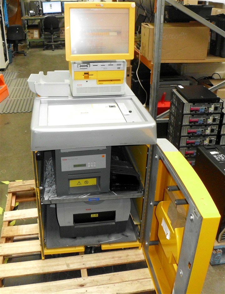
Here you can see the printer in the base of the Kiosk. I am not sure what the printer is today. Back in my time, the printer was a Tektronix Phaser color printer. Instead of toner or ink the printer used solid ink technology and produces color prints significantly faster than ink jet printers. The solid ink comes as cube shaped crayons that melt and are then distributed over the paper to produces a high quality, smudge free and waterproof prints.
Another fascinating product I supported for a short time was the Kodak Retinar X-ray storage system. I can't find any evidence of its existence.
Retinar was a very large camera that photographed full size X-ray films and reduced them to the size of a 35mm slide. The small film was integrated with an IBM punch card. The Retinar camera produced the finished card with the reduced size microfilm along with printed information about the image along the top of the card. The X-ray card was stored and the original X-ray was destroyed. This reduced the amount of storage space needed to archive the larger X-ray films.
Unlike ordinary photographic film, X-ray film is dual emulsion. That means there is emulsion on both sides of the base. This gives the person viewing the X-ray a kind of three-dimensional view of the image. Changing your viewing position changes your impression of the image because of parallax. The small microfilm X-ray produced by the Retinar camera was also dual emulsion. Because it is impossible to evaluate the microfilm X-ray by eye it needed to be evaluated using a desktop viewer. Since it was desirable to view the microfilm X-ray with the three-dimensional effect, the viewer had to have special optics to provide this image. The view screen had etchings that created a fresnel lens. This was supposed to give the doctor or clinician the same perspective as viewing the original larger X-ray.
Retinar only lasted about a year. It was never accepted by the healthcare community as a viable alternative to full-size X-ray film. Kodak took them all back and refunded the purchase. Kodak allowed the customers to keep the viewers along with service support for a reasonable period of time.
This has been a story-telling page. I have no pecuniary interest in telling this story. It is only my memory of a time gone by.
Practically every word on this page is a registered trademark of or copyright of Eastman Kodak Company. This includes but is not limited to the words Recordak, Reliant, Retinar, Imagelink, Starvue, Etakfiche, Ekatprint, Ektalite, Ektamate, Ektachem (and anything with an Ekta in it!) X-Omat, Prostar, Microstar, Lodestar, Komstar, Optistar (and anything with a star in it!), Versamat (and a lot of words with mat in them!) ... you get the point.