

Sometimes my adventures are not involving high tech electronics or software and I have to get my hands dirty.

My garage door opener made a grinding noise and stopped moving the door even though the motor was still running. This was not a good thing. Removing the cover from the opener revealed worn nylon gears and nylon powder all over the place. The opener had a good run. It was installed around 1997.

From the other side more nylon power could be seen. The motor screw drive gear appeared to be good but the mating gear that drives the chain sprocket was badly worn and disengaged at spots.

Fortunately a complete repair kit was only $18 on Amazon. Kit included gear and sprocket assembly, worm gear, grease, motor shaft bearings and sprocket bearings. I was worried about being able to get parts for this Sears/Craftsman opener. Luckily my Sears Craftsman model is a rebranded Chamberlain Liftmaster. It was supposed to come with an installation tutorial. Real men don't need directions so that was not a problem.

Removed the opener from the garage ceiling to work on it on the bench. To replace the parts the process is fairly complex. You can see how much of that nylon powder was created as the gears wore out.
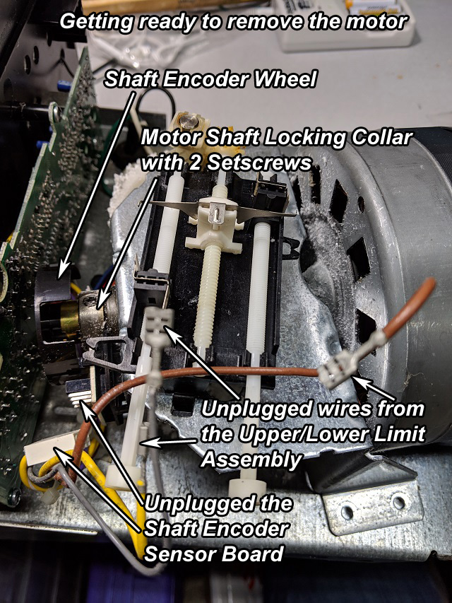
Everything has to be disassembled. The wires were unplugged from the upper/lower limit assembly and the shaft encoder board. The motor and bracker were removed from the main housing.

In order to remove the motor and bracket you have to remove the drive gear for the upper/lower limit assembly. The retaining clip is a small plastic square that has a center pin that acts like a roll pin. There's little torque on this hear so a plastic pin is fine. All the gear does is operate the screw drive that moves an electrical contact back and forth between the door up and door down limit adjustable contacts.

This picture shows how to remove the retaining clip.

With the motor and bracket out of the way you can replace the sprocket drive assembly. The assembly mounts from the outside top of the housing but the three screws come up from the inside.

Here's a view of the old and new sprocket drive assemblies. You can see how badly worn the old one is. This is the gear that mates with the motor screw drive gear,

The shaft encoder wheel just pulls off the shaft. Here it is shown in position with the 5 flags on the wheel passing through the shaft encoder sensor board. This board has an optical sensor with an led emitter and a phototransistor. The flags on the wheel interrupt the optical path and send a pulse stream to the control board to tell the board the motor is running. If the control board has the motor powered on but no pulses are happening then the assumption is that the motor has stalled so shut off the power.

Here's a closer view of the shaft encoder wheel and the optical sensor. You can also see the motor shaft locking collar. This needs to be removed to change the bearing on the other side of the bracket.

Three nuts hold the motor to the bracket. Now you can replace the screw drive gear on the motor shaft. The screw drive gear just slides off.

Take a look at the upper part of the shaft above the gear. The setscrews damaged the smoothness of the shaft here. This needs to be sanded off and made smooth again or you will never get the bearing and collar to go on the shaft. It will take a lot of force to press in the new bearings. If you have to use a hammer to provide extra force be sure not to use a metal one. Use a soft-face hammer with a urethane head. It's like a hard plastic so it won't damage or distort the shaft or bearings.

Everything is reassembled now and the opener is ready for testing. Remember that the opener requires connection to the garage door safety sensor to operate properly.

It looks nice with all the new parts installed. The connector is plugged back into the shaft encoder sensor board and the wires are reconnected to the open/close limit assembly.
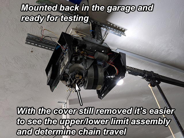
The opener is reinstalled in the garage. At first the motor would not run for more that two seconds. This could be two things. The safety sensor was not working or the shaft encoder was not working. It was not the safety sensor because when there is a safety problem and the motor stops the light will blink on and off. The light was not blinking so it must be the shaft encoder. The control board probably thought the motor was not turning. Upon investigation I determined the shaft encoder wheel was not located far enough down the motor shaft for the flags to interrupt the light beam on the sensor board. After adjusting the motor shaft collar I was able to move the shaft encoder wheel further into the sensor. That resolved the problem.

The next thing before connecting the door to the drive chain was to verify symmetrical travel of the chain on the track with respect to symmetrical travel of the upper/lower limit switch contact. A screw drive moves the limit switch back and forth with respect to the chain travel on the track. Because I removed the chain from the sprocket I lost the reference point between the position of the door connection on the chain to the position of the limit switch. I had to manually position the door link in the middle of the track and position the limit switch in the middle of the screw drive so that both would have equal travel in both directions. I adjusted the upper and lower limits so the door would not fully open or close. Then I gradually adjusted each to achieve full open and full close.
The devices above the opener are connected to the home automation system. The white and blue unit is a Z-Wave door opener so I can open and close the garage door from my cellphone. The other unit is a power module for the Z-Wave device. In case there is a problem with the Z-Wave controller I can perform a remote reset. Below the opener is a camera that can be panned to give me a 360 degree view of the garage.