


Now that I have moved permanently to my retirement home it was time to create a permanent connection to be able to safely use the generator during a power failure. In my former home I installed a second sub-panel and a transfer switch to safely operate the generator. When the home is powered by the generator there can never be the possibility that you could send power back out your house which could injure or kill the power company technicians working on the lines. You need a transfer switch.
 |
| This is the electrical system in my former house. |
| The Main Panel on the right was the original panel installed when the house was built. It was a 200 Amp service. The Transfer Switch has been added in the upper left. It is required to safely switch the house between the commercial power and the generator power without ever allowing the generator power to leave the house and backfeed the wires going to the street. If this happened it could endanger the lives of the power company workers who think they are working on wires that are not energized. A 200 Amp Transfer Switch to switch the whole 200 Amp panel is very expensive. Instead I added a 100 Amp sub-panel and a 100 Amp Transfer Switch. I moved the circuits I wanted to use on the generator from the 200 Amp panel to the 100 Amp panel. I left circuits like electric heaters, attic fan, and other non-essential things on the 200 Amp panel. I installed a 100 Amp breaker in the 200 Amp panel to feed the smaller panel. Only the 100 Amp panel can be switched between the generator and commercial power. This was not a very expensive job because I did the labor myself with some consulting help from an electrican friend. |
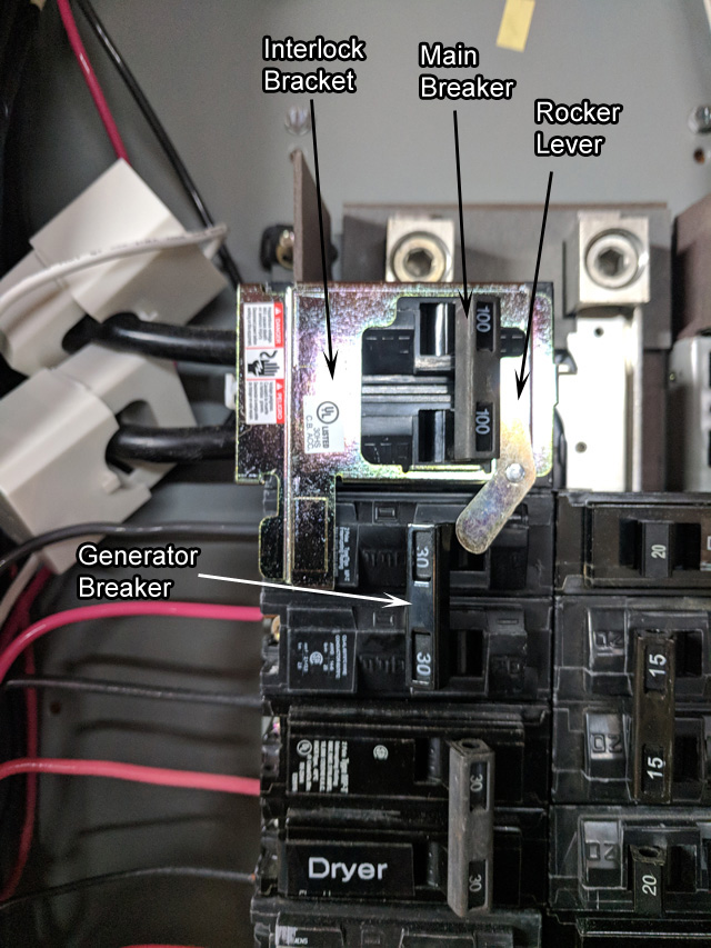 |
| This is the generator connection in my current house. |
| In the new house I have a 100 Amp main panel. Here I took a radically different approach in creating the Transfer Switch. I ordered a specially made interlock bracket which clamps on to the main breaker. There is a rocker lever that drops down to the adjacent breaker just below the main breaker. That's where you install the generator breaker. This rocker lever prevents the main breaker and the generator breaker from both being turned on at the same time. This special interlock bracket was only $29 on Amazon even though it was offered from $75 to $125 on many other web sites. This bracket eliminated the need for an expensive transfer switch and a new sub-panel and the associated labor to wire them. Those two white plastic things on the two main wires are clamp-on current transformers. They are connected to a home energy monitor that feeds electrical information like voltage, current, wattage and kilowatt-hours to my home automation system.. |
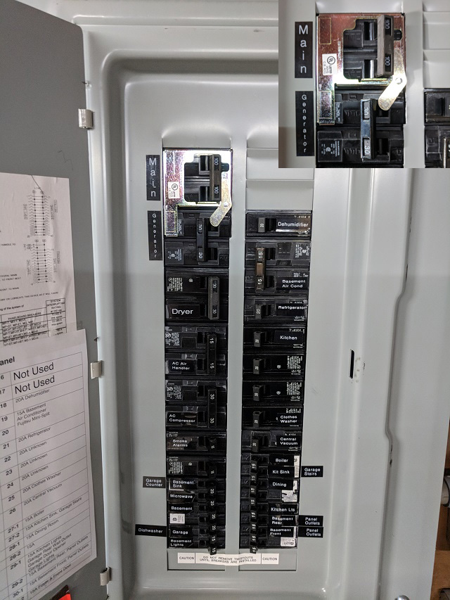 |
| Here is the current panel shown with the cover installed. |
| I had to notch out the center gray bar to allow the best fit of the bracket and allow some clearance for the lever to move. The inset photo in the upper right is a magnified view of the interlock bracket mounted on the main breaker. Notice if you try to turn on the 30 Amp generator breaker the rocker lever will force the main breaker off. When the main breaker is off, trying to turn it on will force the generator breaker off. The only time those two breakers can be in the same position is in the off position. They both can't be on at the same time. |
 |
| Here is the connection receptacle installed outside the house. |
| Because it was less than 75 feet from the panel to the inlet I used #10 three conductor wire with a ground for this 30 Amp circuit. Even with a 20% derating the line should be able to carry 23 Amps. The 5,000 watt generator will only be delivering up to 21 Amps. This wire is really hard to work with because it's so thick and unwieldly. The inlet box is mounted 4 feet above the ground to keep it clear of snow accumulation. The inlet receptacle is located at the bottom facing the ground to keep the water out. There is a power cord that plugs into this inlet and then plugs into the generator. It is important that this cord is long enough to position the generator more than 5 feet from any opening in the house. Remember that sofit vents under the rain gutters are openings! This is to prevent carbon monoxide fumes from the generator exhaust from entering the home. |
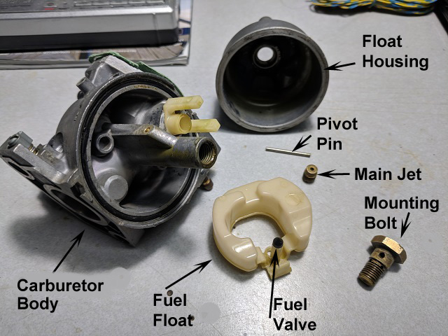 |
| Of course the Honda 5000 watt generator did not start. It had been out of service for some time. I added fresh gasoline and connected the generator's electric start to my car battery. Even with lengthy cranking there was no desire for the engine to start. I poured an ounce of gasoline diretcly into the carburator and tied to start, The engine started right away but only ran for a few seconds. This tells me the engine is not getting gas. I removed the carburator from the engine and disassembled on the bench. Sure enough the main jet was clogged with gunk. In the picture you see the float housing removed. The white piece is the float with the fuel valve (black tip). The bowl fills with fuel until the float rises and the fuel valve stops the fuel flow. The metal pin is the pivot that mounts the float to the body. In the center of the body you can unscrew the main jet. Everything needs to be cleaned of the gunk that forms from old gasoline. |
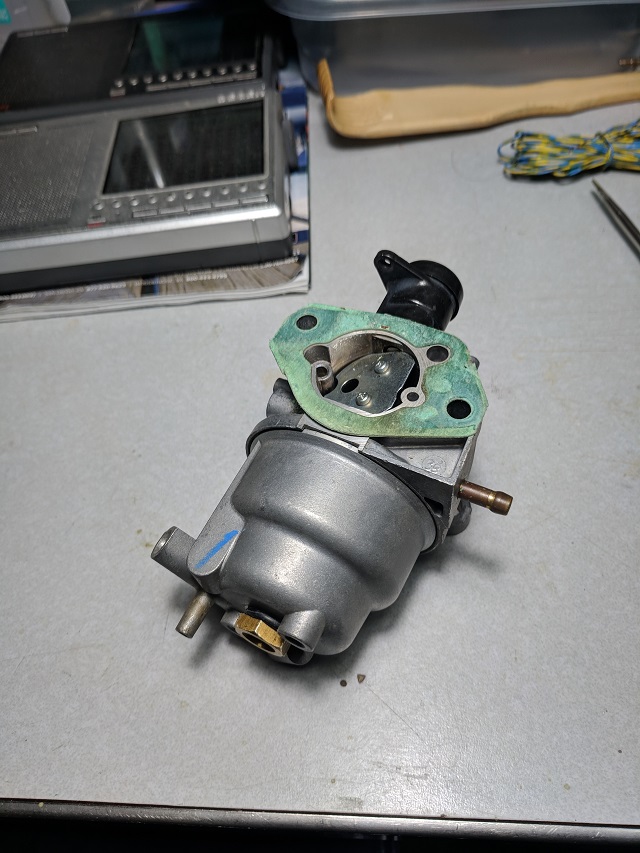 |
| Here's the reassembled carburator. The o-ring that seals the fuel chamber nut was brittle and cracked. I found a similar o-ring but it did not seal well. I installed the cleaned carburator and the engine started right away. However, a tiny amount of gas was leaking from the o-ring. I searched online to try to find a rebuilding kit for this carburator. To my surprise, the whole complete carburator with the fuel cut solenoid and new gaskets was being sold on Amazon for only $17. Since I already went through the learning process and enjoyed the satiasfaction of a proper diagnosis and successful repair I did not think it was cheating to order the whole carburator. I will keep the old one for emergency parts. |
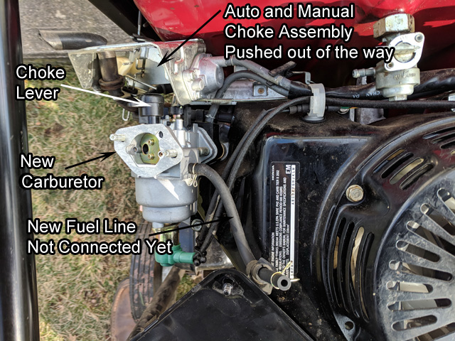 |
| Here is the new carburator installed on the engine. The choke assembly is rotated up and out of the way. This engine has a dual choke that is manual and automatic. When the engine is cold the choke automatically closes. You have the option to manually close it for har start conditions in warm weather. |
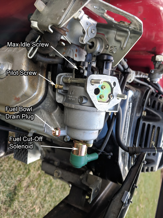 |
| When the choke assembly is rotated down into place you have to connect the choke control linkage to the black plastic cam that controls the butterfly in the carburator. This engine has a fuel cut-off solenout that activates during a low-oil condition to protect the engine. |
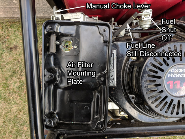 |
| Here the choke assembly is in place the the air filter mounting plate is installed. |
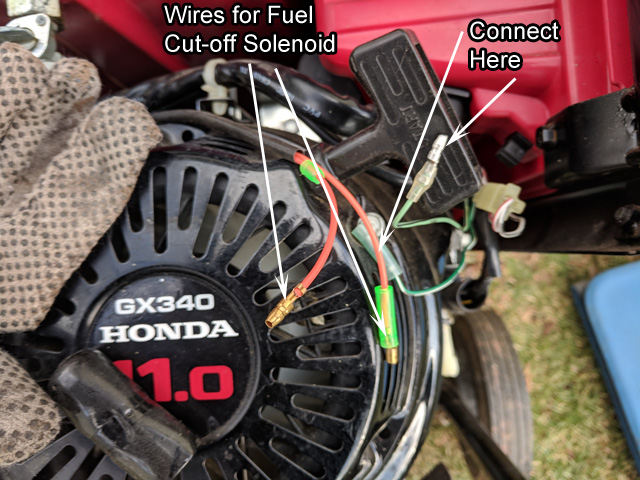 |
| The wires from the new Fuel Cut-Off Solenoid need to be connected to the wires inside the rubber boot on the right side. The next picture shows the boot with the wires installed. |
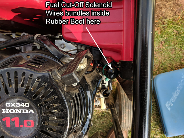 |
| The boot was re-installed with a new wire tie. |
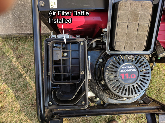 |
| The plastic inside baffle plate is installed. |
 |
| The Air Filter is installed on the baffle and the cover is installed and clipped. |
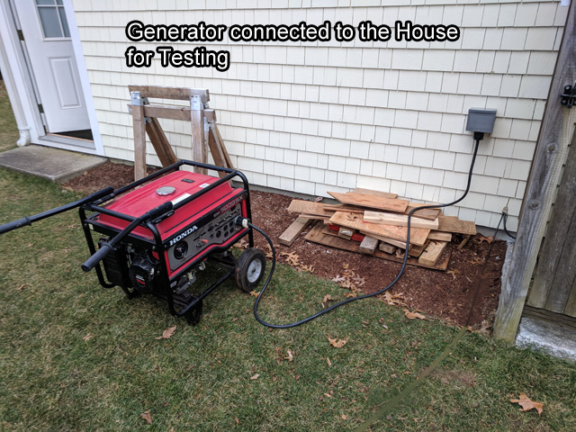 |
| The generator was connected to the house. It started on the second pull. Before the house was switched over to the generator some measurements and adjustments were needed. |
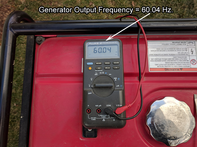 |
| I did not have a tachometer to set the engine idle to 3600 RPM but my multimeter can measure the generator power frequency. I adjusted the engine idle speed to achieve a nominal 60 Hz. frequency. At that speed the generator was producing 129 volts on each phase. |
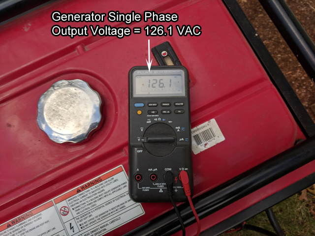 |
| After switching the house on the generator output voltage dropped to 126 volts. As I switched the house from commercial power to generator power I was able to verify the proper operation of the interlock lever on the breakers. It does indeed force off the main breaker if you turn on the generator breaker. It looks like I will be ready for the next power outage. I drained the fuel tank and the carburator fuel bowl. I plan to get a gallon of aviation gas to pour a small amount into the system after being used just to keep old gasoline from gunking things up again. |