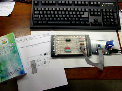
I got bitten by the bug again. Over 16 years ago I developed a microprocessor system to control my Ham Radio repeater. I have not really done much hardware or software development since then. Things sure have changed. I obtained a Parallax Propeller development board to start learning more about this fascinating chip. [I am not affiliated with Parallax. Any views or opinions presented here are my own, including my excitement.]

[From the Parallax Web Site:] The Propeller chip makes it easy to rapidly develop embedded applications. Its eight processors (cogs) can operate simultaneously, either independently or cooperatively, sharing common resources through a central hub. The developer has full control over how and when each cog is employed; there is no compiler-driven or operating system-driven splitting of tasks among multiple cogs. A shared system clock keeps each cog on the same time reference, allowing for true deterministic timing and synchronization. Two programming languages are available: the easy-to-learn high-level Spin, and Propeller Assembly which can execute at up to 160 MIPS (20 MIPS per cog).

The development board is on the right. Just plug in a 9V power supply and a USB mini cable. Download the free Propeller Tool Software and you will be sending demo programs to the onboard EEPROM over USB in no time. The Propeller Tool Software is a full-featured Integrated Development Environment (IDE) that consists of an editor, complier/assembler and USB and serial downloader. Parallax also provides a terminal program so you can interact with the Propeller in real time through a console window.

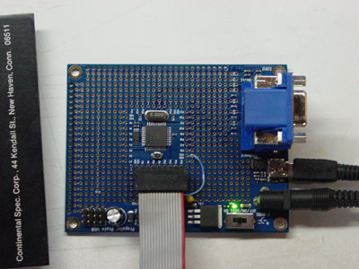
This is a view of the Parallax 32812 Propeller Proto Board USB. Notice the 15-Pin VGA connector in the upper right. Below it (not seen) is a PS2 Keyboard connector and a PS2 mouse connector. After firing up the Propeller Tool Software I had graphics and text being displayed from some of the demo programs in a matter of minutes. I wanted to try my hand at lighting some LEDs. I soldered a 16 pin DIP socket in line with 8 I/O pins so I could bring a ribbon cable out to the proto board below.

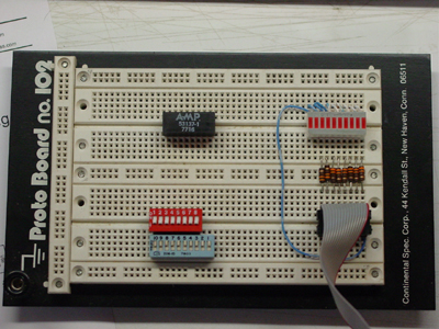
Here on the right side of the board I installed a ten segment DIP led display with eight dropping resistors. I had those LEDs blinking on command in no time. I plan to write more about this as I have some time to become familiar with this exciting device. My hope is to develop some useful home automation applications that will include remote monitoring over the Internet.


