


Back in the 1980s I experienced many opportunities to apply my interest in digital circuits to practical uses.
My employer had a buisness telephone system that had four incoming telephone lines our customers could use to place service calls. Any calls coming in on any of the lines would be routed to the next available dispatcher. During nights and weekends we needed to record incoming calls but more importantly, we needed to know if anyone was calling the office when there were no dispatchers on duty. If an employee such as a manager was working late and needed to be contacted, incoming calls would be directed to a dispatcher's desk. We needed a way to signal the employee to pick up the incoming call at his or her desk.
That's where I came in. I had prior experience interfacing my ham radio equipment with phone lines. I designed a circuit that would monitor the four incoming phone lines. If any line had an incoming call and was "ringing" the circuit would ring a loud bell in the ceiling and switch the line over to a single line answering machine. If nobody answered the call in time, the answering machine would pick up and record the call. After the caller hung up, the circuit would detect the hang up and reset everything for the next call.
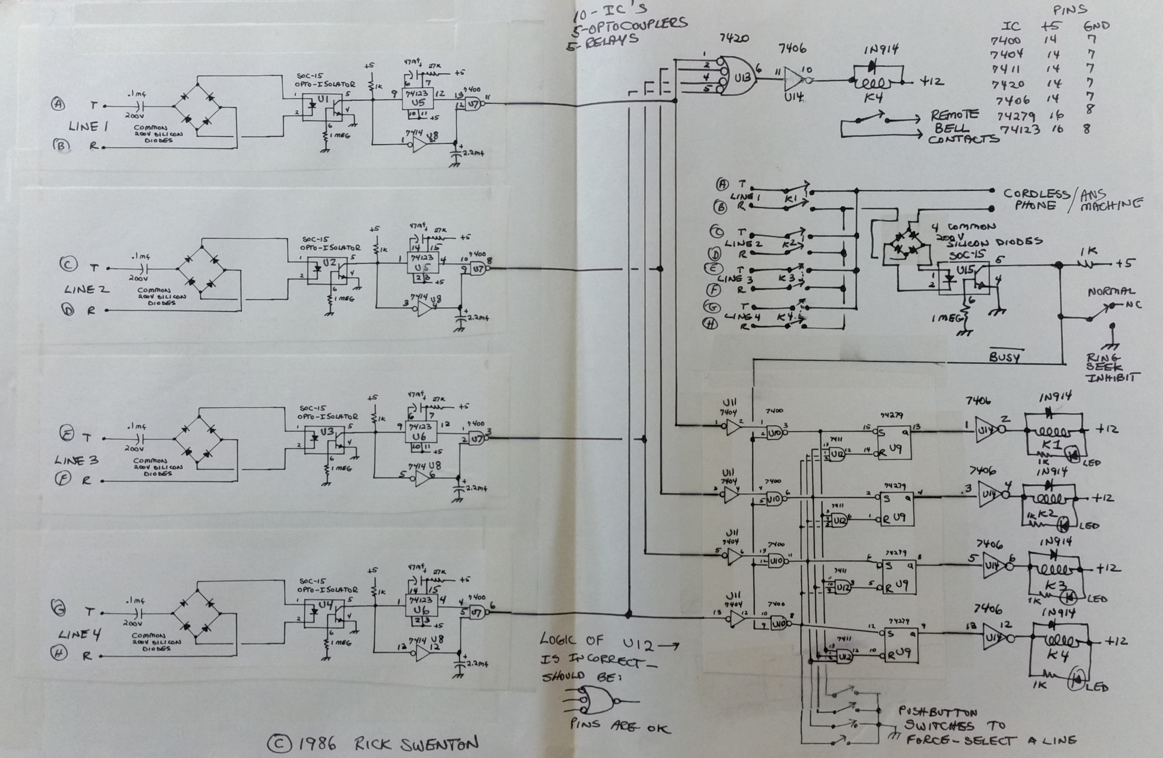
This complex circuit is really one circuit multiplied four times. You will notice I actually drew a part of the diagram, made three copies, and cut and pasted those on the main drawnig. At the left, there are four optically isolated ring detectors connected to each of the four phone lines. The isolation is needed to protect phone company employees and also to protect my circuit from static and nearby lightning pulses. The 74123 ICs debounce the signal for further noise suppression. At the top, U13 will ring the night bell when any of the lines have an incoming call. At the bottom right, an incoming call will latch one of the four RS Flip-Flopps at U9. This will connect the line with the incoming call to the answering machine which will record the call if nobody answers it. Slightly below the top right is another opto-isolator. This is a phone line current detector. When the calling party hangs up, the phone line will briefly interrupt its current flow. This will reset the circuit and make it ready to accept a new incoming call.
Optoisolators are great. The transmission of the needed signal is done with a light beam inside the IC. No actual physical connection exists between my circuit and the phone line except for the dry relay contacts that switch the four lines to the single line answering machine.
There is an FCC requirement that only approved devices could be directly connected to the public telephone system. The attached device needs to prevent electrical hazards to phone company personnel, damage to their network equipment, malfunction of their billing equipment, and degradation of service to other phone company customers. My circuit does all this but it was not certified and certainly was not in the FCC database!
Today you can purchase an approved interface component that sits between the phone lines and your circuit. Today you could also perform everything this circuit does with a $15 Arduino board, a simple C program (sketch) and a few extra parts.