The Automated Home seems to be undergoing constant upgrades these days.
Here is a chart of the current Automated House functions. The system uses a combination of older X10 powerline control devices and more modern Z-Wave devices along with specialty devices like web-based relays, hard-wired Arduino and Raspberry Pi I/O interfaces and wireless environmental sensors.
| Function | Method |
| Remote Control | Web-Based Interface HSTouch Smartphone App for Android and iPhone. IFTTT Integration. |
| Alexa Integration | Alexa voice control with smart speakers in four rooms. |
| Security System | Doors and Motion Sensors. Cameras. E-Mail and SMS Alerts. All lights on with security breach. |
| Occupied / Vacant Mode | Vacant Mode performs Thermostat Setback, Main Water Valve Off, unnecessary devices Power Off, changes Lights Schedule. |
| Power Monitoring | E-Mail and SMS Alert. Monitoring of power usage and demand. Weekly, Monthly and Yearly graphs for demand and cost. Monitoring of commercial power, generator and transfer switch status. |
| Low Temperature | E-Mail and SMS Alert. |
| Boiler and Water Heater | E-Mail and SMS Alert for low temperature. |
| Smoke, Carbon Monoxide, Natural Gas Alarms |
E-Mail and SMS Alert. |
| Water Leaks | E-Mail and SMS Alert, automatic water shutoff. |
| Main Water Valve Control |
Web-Based and Smartphone Control. |
| Thermostat Control | Web-Based or Smartphone Control. Three heat zones, central air conditioning, Mini-Split Air Conditioners and basement Central Dehumidifier. IFTTT control of Mini-Split Air Conditioners.. |
| Freeze Protection | Redundant mercury thermostat fail-safe in case of automation failure. |
| Lights/Appliances | Web-Based and Smartphone Control / Computer Schedule for lived-in look. Macros. Z-Wave Scenes and Associations. |
| Front Door Lock Rear Door Lock Shed Door Lock |
Web-Based and Smartphone Control plus Manual Keypad and physical Key. Remote code programming, |
| Garage Door Opener |
Web-Based and Smartphone Control plus Manual Keypad/Camera (MyQ) |
| Environmental Monitoring | Indoor and Outdoor sensors for wind speed, wind direction, rainfall, temperature, humidity and barometric pressure. Temperature Sensors in all rooms and in the Attic and Garage and outside. Humidity sensors in many rooms. |
| Irrigation System | Web-Based and Smartphone Control and IFTTT. |
| Video Cameras | Web-Based and Smartphone Viewer. Outside Front, Two Outside Rear, Kitchen, Living Room, Garage, Workshop. |
| Diagnostic Tools | SMS and Email Alerts for device outages and various malfunctions. |
| Audio Devices | Lyrion Music Server (LMS) with vaious Logitech Squeeze Box Radios and Duet Receivers. Raspberry Pi based players. Smartphone control. Automatic power control for amplifiers. Alexa integration with smart speakers and Echo devices on stereo systems. |
| Battery Backup | Uninterruptible Power Supply (UPS.). There is a 10 second delay for the generator to start when the power fails. The UPS provides backup power for the server, NAS storage, cable modem, VoIP phones, router, switches and some cameras during the 10 second outage. |
Let's look at the details of the automated house.
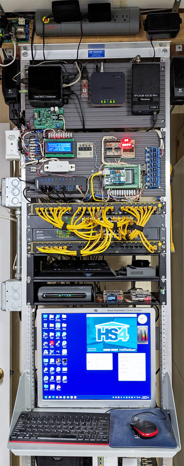
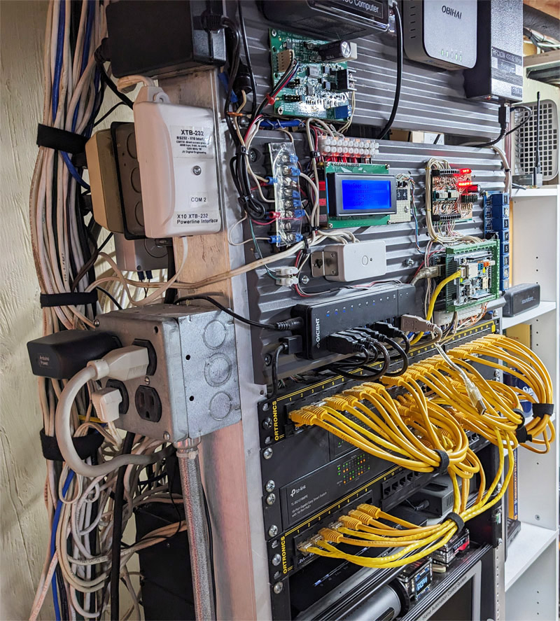
This is a picture of the network rack The display shows HomeSeer HS4 running.
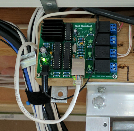
This is the four relay network control board. This board is reachable remotely as long as the internet is up and is independent of the NUC computer. One of the relays is wired directly into the Intel NUC computer's power supply so I can power the computer off or on to force a reboot remotely in case of a problem. The NUC is set to resume on power up and wake on Lan. You can see DC power and ethernet connections on the bottom and dry contact terminals on the left side. Simple.
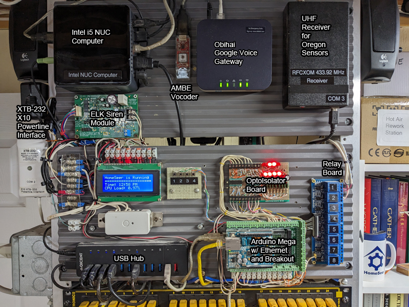
On the left is an Intel NUC (Next Unit of Computing) Module. The NUC is a small 4" x 4" x 2" low power consumption full-featured computer. This is the brains of the operation. It runs Windows 11, Homeseer HS4-Pro, Logitech Media Server and other software The one I purchased, NUC8i5BEH, has the following specs:
- 8th Generation Intel® Core™ i5-8259U Processor
- 4 core - 8 threads
- Intel HD Graphics, HDMI and USB-C
- 16 GB Intel Optane memory accelerator (DDR4 memory is required and must be purchased separately). Intel Optane memory automatically learns your computing behaviors to accelerate frequently performed tasks
- M.2 22x42/80 (key M) slot for SATA3 or PCIe X4 Gen3 NVMe or AHCI SSD
- 2.5" SSD/HDD bay. USB 3.1 Gen2 (10 Gbps) and DisplayPort 1.2 via USB-C
Below the NUC is an ELK Voice Siren module driving the alarm speakers in the house. To the right of that is an NWDR ThumbTV AMBE 3000 Vocoder module. This device allows me to use computers with microphones and speakers to communicate over Digital Ham Radio using DMR, DStar, NXDN and YSF protocols.
On the far right is the RFXCOM UHF receiver. This device receives signals from my Oregon Scientific environmental sensors such as temperature and humidity sensors as well as the outdoor weathervane and rain sensor.
At the middle left is the XTB-232 X-10 Powerline Interface. This device sends and receives X-10 signals to control or listen to older technology devices that communicate over the powerline. The XTB-232 is an aftermarket replacement for the CM11a interface sold by X10. It is more reliable and delivers a more powerful X10 signal into the power line. Over time I replaced almost all of my X10 devices in the house with Z-Wave.
Moving to the right is an LCD display that displays a bit of status, the white Z-Wave power switch that controls the voice / alarm siren, and a USB Hub.
Finally we have the Arduino Mega, OptoIsolator board and Relay Board. The house originally had a legacy Apco hard-wired alarm system that was in a state of disrepair. The controller required external service equipment to update. Never letting good existing wiring go to waste, I decided to continue to use the wired door switches and wired motion sensors for my HomeSeer alarm system. I used an Arduino Mega to monitor the wired signals and communicate their status those to HomeSeer. The OptopIsolator board provides an isolation between the wired sensors and the electronics by passing the signal with a light beam inside the circuit chip. Two ILQ74 Quad Optoisolators are used for 8 input channels. The 8 LEDs are lit when the loops are clsoed. This board prevents the long wire from acting as an antenna picking up noise and possibly falsely activating a signal. It also minimizes the effect of my radio signals interfering with the system. The Arduino also operates a bank of 8 relays for additional control flexibility. Besides monitoring the wired door and motion sensors, the Arduino also monitors the Smoke/CO alarms, the heating system zone valves, the generator and transfer switch status and A/C condensate pump alarms.
[ Home | Top ] Here's a close-up view of the NUC with the Optane memory which is a type of flash storage that helps speed up applications.
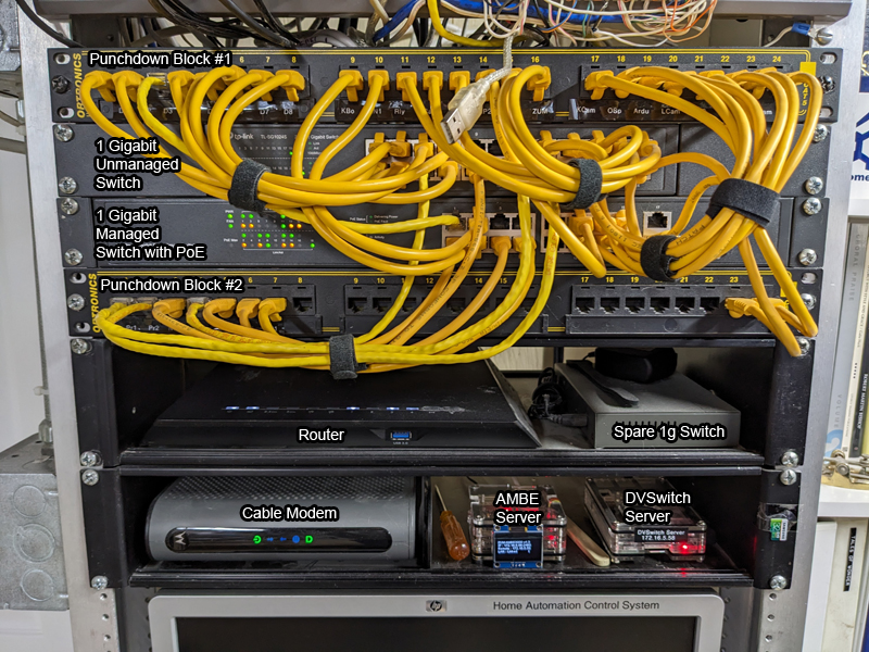
Continuing on down the rack we have the ethernet punchdown blocks and patch panel. The punchdown blocks provide a place for the wires on the ethernet cables to be connected to an RJ45 network jack. The yellow patch cables allow each jack on the punchdown to be connected to a desired port on one of the switches. The top switch is a gigibit unmanaged switch. The bottom switch is a managed gigabit switch with Power over Ethernet (PoE). PoE provides power to devices like cameras, phones and Raspberry Pi computers right over the ethernet cable. In the picture you can see the cable modem and router. The AMBE server and DVSwitch server are Raspberry Pi computers and are used for digital Ham Radio communications.
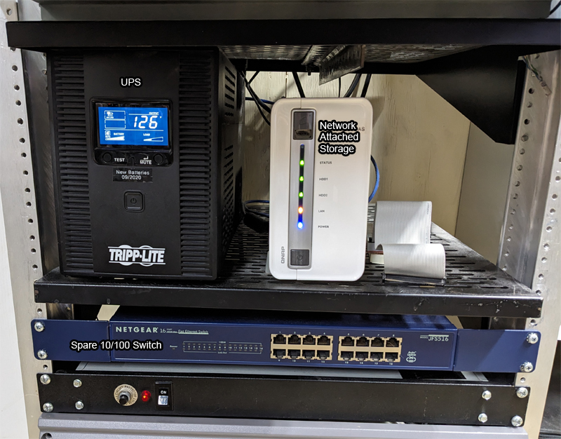
At the bottom of the rack is a Tripp-Lite Uninterruptable Power Supply (UPS) which provides battery backup power to the system. There is also a Network Attached Raid Storage array.
Using an RFXCOM 433.92 MHz receiver some of the environmental monitoring is done with wireless Oregon Scientific devices designed to be used with a Weather Station. I only have the sensors. There is a temperature sensor in every room, in the attic and on the boiler. The sensor in the living room senses temperature and humidity plus barometric pressure. Outside there is a temperature and humidity sensor on the house designed for outdoor use. The weathervane that reports wind speed and direction has rechargable bateries and a solar panel to charge them so I don't have to get out the ladder to change the batteries. So far, it has been running this way since 2016.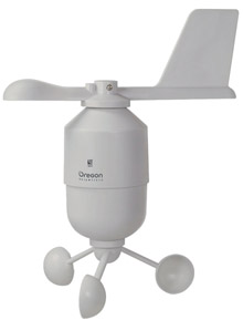
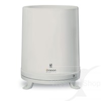
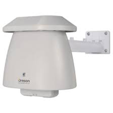
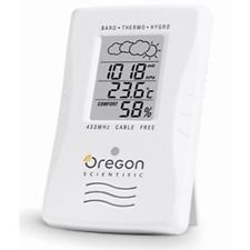
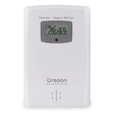
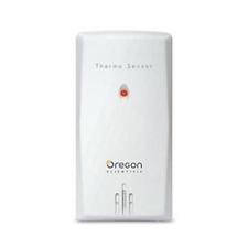
These are some of the Oregon Scientific environment sensors I have around the house. The outdoor sensors are the top three: WGR800 Wind Speed / Wind Direction, PCR800 Rain Gauge, and THGN801 Outdoor Temperature and Humidity. The bottom three are the indoor sensors: BTHR918N Temperature / Humidity / Barometric Pressure, THGN122 Temperature / Humidity and THN132 Temperature with no local display,
The wireless motion sensors are Aeotec Z-Wave Tri-Sensors. They detect motion and report temperature and light level (lux). The door sensors are the original alarm system's door switches that are hard wired into the Arduino Controller.
[ Home | Top ]
Home Control Quick View
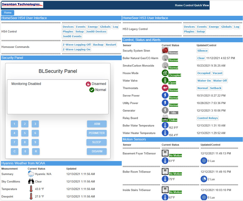
Above is a partial screen shot of the Homeseer Web interface. Sorry about the resolution. It's a very long page and hard to fit here in the article. Click Here for the HomeSeer Web Control for a better resolution screen shot. Then use your cursor and press on the + to zoom in to the picture. This page is actually four browser screen pages long. You can see the controllable devices with the ON and OFF buttons (some with the ability to set the dim level) and an abundant amout of data from the environment and security devices. Of course, the buttons in the picture here on the web site don't actually operate things in my house!
[ Home | Top ]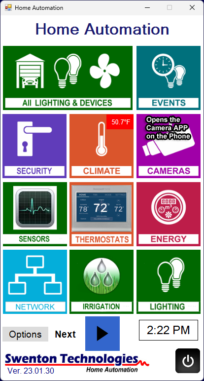 Above is the Main Menu Screen of my Homeseer HS4 implementation using their HSTouch Application on a smartphone. I created a simulation of this system that runs on my Android phone that you can experience using the link below. For these screens I used Homeseer icons or personally modified / customized Homeseer icons. The HSTouch server- is built into Homeseer HS4. The client can be an Android, IPhone or Windows running the HSTouch client software. It's not for the faint of heart to get the results I am showing here. Many hours of work have gone into the design and functionality of the screens. It may not be obvious in the demo but the general Back Button to go backwards through the screens is the Swenton Technologies logo at the bottom of the screens. It shows "Back" on the logo at the bottom left corner when available. Of course, the control buttons in the demo don't actually operate things in my house!
[Climate Screens with active gauges updated 11-01-2024]
Click Here to enter my HSTouch Demonstration
[ Home | Top ]
I selected the OpenSprinkler device as my irrigation controller. It is economical and comes with smartphone software for remote control. Further, there is a plugin for Homeseer to interface with the controller. 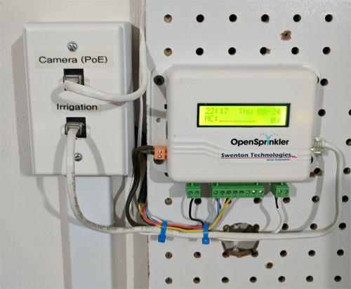
This device comes in several configurations. One is Arduino based. Another is Raspberry Pi based. I purchased the classic version which operates 24 VAC valves and powers up from the systems 24 VAC transformer. The latest version runs on either USB 5V DC power or a provided 12 VDC power supply. It can control AC or DC valves but you need to provide your own power for the valves.
Opensprinkler can be completely controlled remotely using their smartphone app. There is an Opensprinkler plug-in so it can also be controlled using Homeseer both on the Homeseer web page and using Homeseer HSTouch on a smatrphone. This gives versatility, flexibility and convenience.
Opensprinkler has an option to allow automatic adjustments to the watering schedule based on the weather. It also has an input for a rain sensor to tell the system not to water if it is too damp already.
[ Home | Top ]
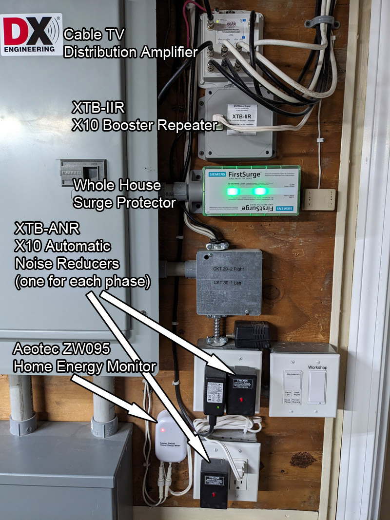
On the right side of the breaker panel we have the XTB-IIR X-10 Amplifier-Repeater, two XTB-ANR X-10 Automatic Noise Reducers (one on each phase) and the Aeotec Z-Wave Energy Meter. The clamp-on current transformers for the energy meter are inside the breaker box. They are clamped on each leg of the 220v mains entering the box.
[ Home | Top ]
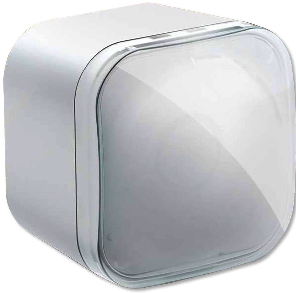
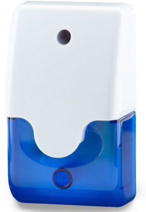
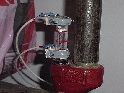
The WaterCop system consists of an electronic shut-off valve and three wireless, battery-operated WaterHound probes. The shut-off valve installs on the home's main water line, right after the main shut off valve. The electric water valve plugs into any standard 3-prong power outlet and features green and red LEDs indicating if the water flow is open or closed.
On the WaterCop front panel you can see the Open/Close membrane switches and indicator LEDs. You can also see the RJ-45 jack that interfaces the WaterCop to the Z-Wave relay modules so I can operate the valve through HomeSeer. This jack also provides an output signal to indicate the open/closed state of the valve.
The Water Cop radio antenna is extending below the WaterCop motor. That antenna is so that the valve can receive water leak signals from the WaterHound probes. The black antennas sticking up from the two relays are Z-Wave antennas.
On the RJ45 jack there are both inputs and outputs. You can manually control the valve by the membrane switches on the front of the motor, or you can wire in a single pole double throw switch to control the valve remotely, such as from the primary entrance to the house. For those who like to shut the water off in their vacation house before they leave, having this feature at the main entrance is convenient. There are also signal outputs to light indicator lights at the remote location which show the current open or closed status of the valve. These outputs can also be used to send a signal into a monitoring system to alert you when the valve has been closed. I don't use these signals because I shut the water off when the house is unoccupied.
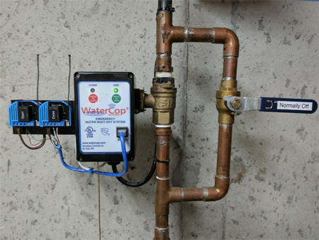
The WaterCop electric valve is the black box on the left side of the pipe, mounted on a ball valve. This is the version for 3/4 inch pipe. The house main water valve is located below the WaterCop and is not visible. To the right of the WaterCop I installed a bypass valve so that I can manually override a shutoff caused by the electric valve. Although you can manually open and close the electric water valve simply by pressing the open or close buttons on the motor housing, I thought it was prudent to install a fail-safe mechanical bypass for those times such as when the power is out. If you don't want a bypass valve, you can turn the water back on without power by removing a retaining clip, removing the motor assembly from the ball valve, and turning the valve on with a screwdriver. To the left of the WaterCop you can see I mounted two Qubino ZMNHND3 Z-Wave relay modules. These modules are really small. They are the size of a camera battery. I needed two relays to control the open/close functions of the electric water valve. I obtained two of the single relay models because I heard there were problems getting both relays on a dual relay module included in certain Z-Wave systems. Plus, the dual relay module did not provide isolated contacts from the AC line. I purchased these because they have isolated dry contacts. That means none of the relay contacts are internally connected to the AC line. I also wanted to use the configuration parameter to make the relay automatically turn off after 1 or 2 seconds so it could act like an electric push button. I connected one set of relay contacts to the Water Cop's remote OPEN connection and the other set of relat contacts go to the Water Cop's remote CLOSE connection. In order for HomeSeer to operate the OPEN/CLOSE function you send an ON command to the OPEN relay to open the valve and you send an ON command to the CLOSE relay to close the valve. These Qubino modules can be configured to return to the OFF state after a predetermined time. I set the modules to return to the OFF state after two seconds. Now the relays send either a two second OPEN signal or a two second CLOSE signal to the water valve. I mounted the relay modules on a bracket screwed to the side of the WaterCop valve. I also provided AC power to the modules by running a power cord into the WaterCop and tapping into the 110 VAC power there,
Today you can purchase Z-Wave ready water valves. I would have not gone through this trouble if I did not already have the valve!
These Relay Modules are operated in conjunction with the Home Automation's Occupied/Vacant function. A Home Seer macro event has been programmed so when it receives the remote command that the house is vacant, HomeSeer turns down the heat on the Z-Wave thermostats and it tells the WaterCop water valve to close. When HomeSeer receives the remote commend that the house is occupied it signals the Z-Wave thermostats to return to normal temperatures and signals the WaterCop water valve to open. The workshop air conditioner is also forced off when the house is unoccupied using this macro.
Now let's move on to the Heating System.
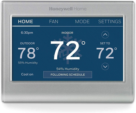 Each of the three hydronic heating zones and the central air conditioning are controlled by Honeywell-RTH9585WF Wifi Thermostats. Using these thermostats allows me to control the heating and air conditioning remotely using a web browser or smartphone apps for Android or iPhone. The living room thermostat is the only one that controls the central air conditioning for the first floor. You will need the "C" wire from the system to power these devices. That means for heating only, you will need 3 wires: Rh, W and C. For cooling you would add Rc, G and Y. HomeSeer has a plugin that allows me to operate these thermostats through Homeseer. That means I can control them and read values from them. These values can trigger HomeSeer events if desired. I can control these thermostats over the internet using their Total Connect Comfort app as well as through Homeseer using the web interface or the HSTouch system on my phone.
Warning! Use a competent professional heating contractor for all updates or repairs on a heating system.
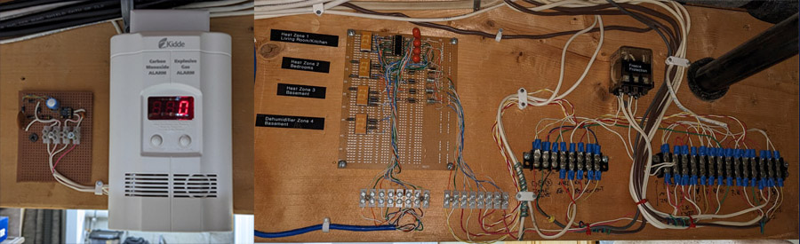
Here's a picture of the rewiring of the thermostat and zone valve connections. The original was a ball of twisted wires and wire nuts. This one is more organized and neat but will probably drive most HVAC technicians out of their mind because it is out of the ordinary. There are three zones for hydronic heating and a fourth zone to monitor the basement central dehumidifier. On the left is a Carbon Monoxide and Natural Gas Detector with an opto-isolated interface board wired to the Arduino Controller on HomeSeer. If Smoke, CO or Natural Gas is detected in the boiler room, HomeSeer will receive a signal from the interface board. The board simply connects to the transducer in the alarm, rectifies and filters it. When the alarm sounds, the transducer provides a voltage to operate an optoisolator that in turn connects to the Arduino at HomeSeer. The large relay on the upper right is wired to a conventional mercury thermostat in the center of the house. That thermostat is set to 50 degrees F and is used as fail-safe freeze protection. If that thermostat operates, both zone valves will be activated and it will override the Wifi thermostats. This was primarily a safety net that gave me peace of mind when I did not live here full-time.
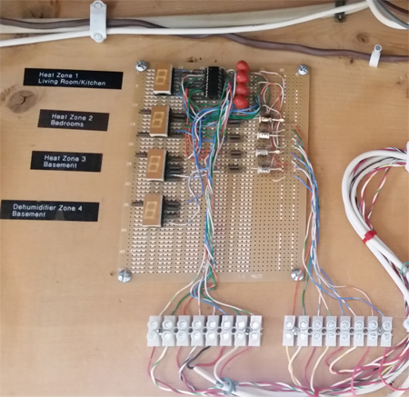
Here's a closer view of the heating zones interface board. There are four 7-segment LED displays that light up 1-2-3-4 to indicate which zone is active. The 24 VAC feeding the zones is converted to an open collector output that drives the Digital Input Ports of the Arduino Controller so that the home automation software can know and display the state of the four zones.
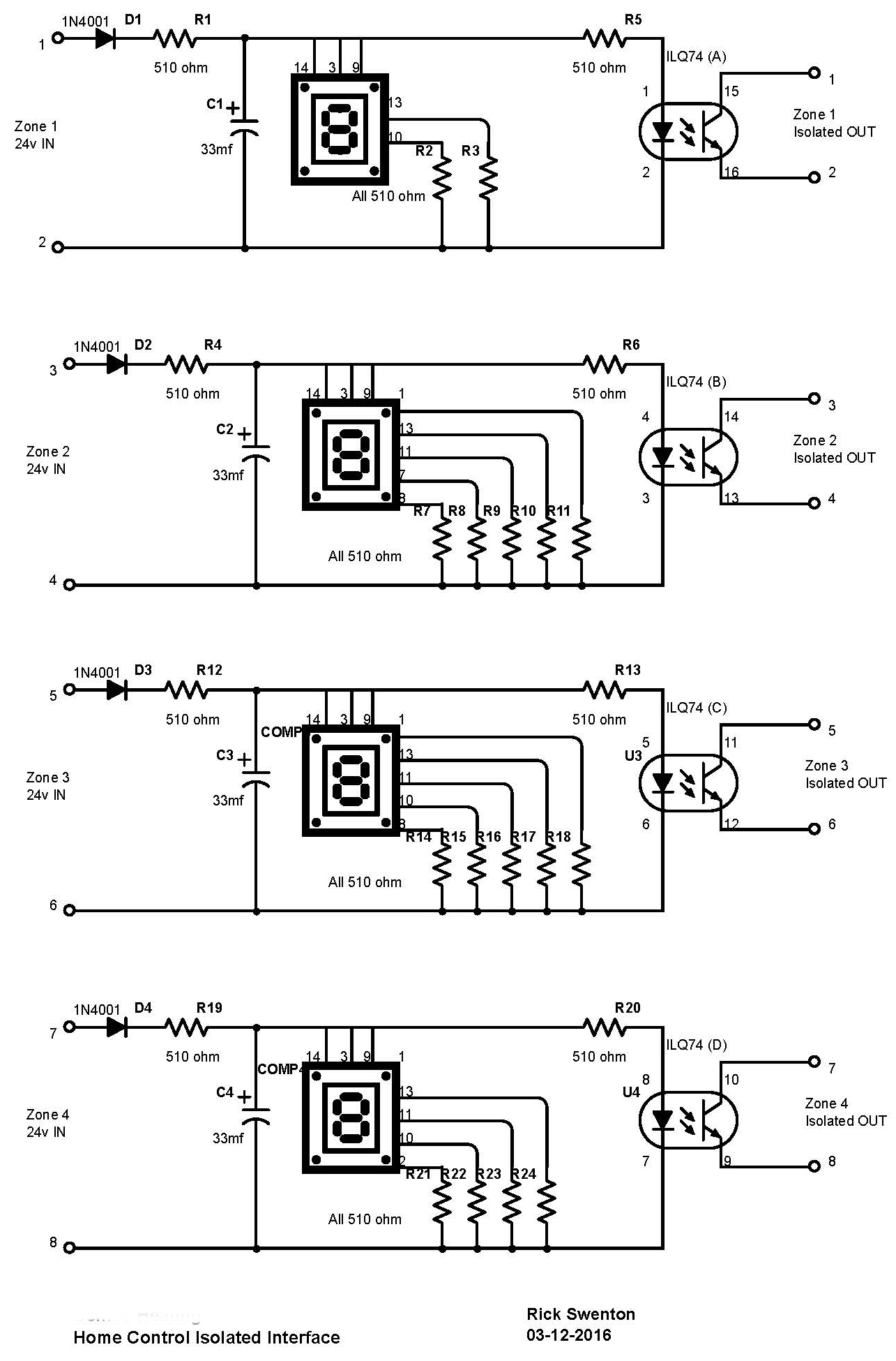
Here's the diagram of the heating sysetm interface. The inputs on the left connect to the zone valve coils. The open collector outputs on the right connect to the Digital Input Ports of the Arduino Controller. They are totally isolated from the heating system and look like dry contacts to the Ardiono. I use the 4th zone to indicate the status of the basement central dehumidifier. The dehumidifier has a dry relay contact that closes when the system is operating. I just wired that in series with the Zone 4 inout and the 24 VAC voltage from the heating system. The LEDs offer a primitive display where they are hard wired to display 1-2-3-4 respectively. The ILQ-74 IC is a quad optoisolator. It is virtually equivalent to four 4N25 ICs. The optoisolator output is not a true dry contact because it is a transistor and only conducts current in one direction. If the optoisolator is turned on but the Arduino input port does not respond, simply reverse the connection of the two conductors. On the Arduino input ports the emitters of the optoisolators should go to ground and the collectors should go to the inputs.
Warning! Use a competent professional heating contractor for all updates or repairs on a heating system.
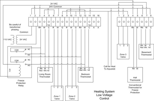
This is the heating system low voltage connections diagram. The interface board previously shown connects to the three zone valves at pins 1 and 2. These pins have 24 VAC applied when the thermostats are calling for heat. The 24V is sent into the interface where it is rectified and filtered to DC and then optically coupled to the home automation system.
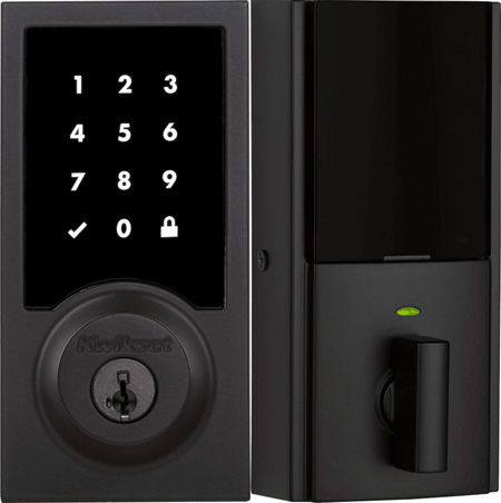
For the front door lock I selected the Kwikset 916 Z-Wave lock. This lock replaces the conventional deadbolt and runs on four AA batteries. One of the reasons I chose this lock is because the rest of the house has Kwikset SmartCode locks. These lock cylinders can be easily re-keyed using a simple tool inserted into the tiny slot in the front of the lock. So it's simple to make all the house locks use the same single key. This lock can be opened with a Z-Wave command over the Homeseer system, by punching in the access code on the lock's front keypad, or with the physical key. You can have several different access codes if you desire. For example, you can set a code for a conractor or service person to enter the house and then delete it when the event is complete. You can lock the door with the inside knob. From the outside you can lock the door by pressing the lock button. No code is needed to lock. Of course you can always use the key and knob, even with dead batteries. The AA batteries drop to about 50% in about 6 months. The lock periodically reports its status over Z-Wave and it immediately reports its status if manually operated.
For the Garage Door Opener interface I chose the Teleguard GDC1 Universal Z-Wave Garage Door Control Switch. The Teleguard GDC1 Universal Z-Wave Garage Door Control Switch is neat because it looks like a plain Z-Wave binary switch. You open or close the garage door just like you would turn a light on or off. You know that a garage door opener uses a single push button. Push to open. Push again to close. The GDC1 comes with a wired magnetic door sensor so it knows is the current state of the door. This allows you to change the single button logic to a dual open/close logic like a toggle switch. When you remotely request to close the door a warning alarm sounds and a strobe light turns on for about five seconds before the door starts to move.
The only minor problem was that the state of the GDC1 in Homeseer only reflects it's last remote operation. For example, if you opened the door with the GDC1 and then closed it with the wall switch, Homeseer would show the GDC1 is an opened state. Even polling the device did not return the real door status. This was easily resolved by adding a second magnetic switch to the door to feed the real-time door status to Homeseer.
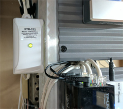
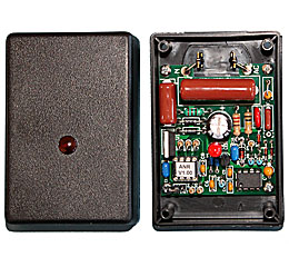
My original home automation system used the older X10 technology. The XTB-232 which is a direct replacement for the X10 CM-11a X10 Interfacce. This interface is needed to allow Homeseer to communicate over the powerline to X10 devices in the house. Homeseer sends and receives X10 commands which are processed by the XTB-232 and reformatted to native X10 protocol to operate Lamp Modules, Appliance Modules, Wall Switches, Wall Dimmers and more. The XTB-232 is available assembled and tested for $109. Jeff's web site is at http://jvde.us/ The serial cable from the CM11a will work with the XTB-232. If you need a cable it is an extra cost.
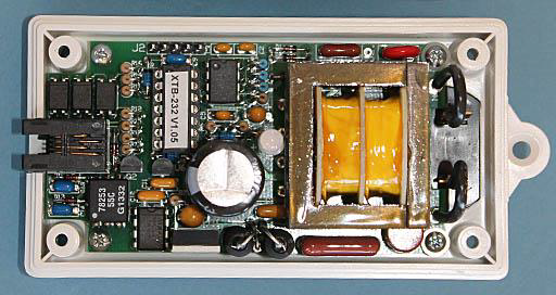
The XTB-232 is another very fine product from Jeff Volpe. Here's an internal view of the device. You can see the superior quality and thoughtful design. You can't go wrong with Jeff's products. Throughout all of his designs he is ultra conservative in selecting the rating of the components.
I built the kit version of this product, the XTB-IIR and two XTB-ANRs. I was very impressed with the quality of the components, the design, and especially the performance.
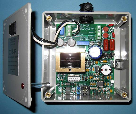
X10 is an old technology that transmits control signals through the power line. In today's homes there are a lot of sources of interference and noise on the power line. Reliable X10 communication requires amplification of the signal and a method of bridging the signal from one leg of the split phase 220V system to the other leg.
A state-of-the-art X10 active coupler is sold by Jeff Volpe of JV Digital Engineering. The XTB-IIR is a high-power 2-phase X10 repeater. It has two coupling networks to drive high power signals onto both phases. The X10 Boost input on the cover will directly boost the output of an X10 transmitter. It will repeat any valid X10 commands it receives over the powerline.
The XTB-IIR has a large power supply. Its powerful transmitter delivers over 20 times the output power of typical X10 transmitters to greatly improve X10 performance and system reliability.
The XTB-IIR emulates the X10 TW523 and PSC05 two-way interface devices which have become harder to find. It accepts the same RJ11 plug that the other devices have.
The XTB-IIR is no longer available. Check Jeff's web site is at http://jvde.us/ He may have a refurbished unit. He does have other power boosting options.
Another essential device desired for proper X10 operation is Jeff Volpe's XTB-ANR. The XTB-ANR continually monitors the powerline for PLC signals, and will switch off its attenuator when an X10 or Insteon signal is recognized. One plugged into each phase near the distribution panel it will significantly reduce the overall noise levels throughout the home, including any coming in over the utility feed. You will need two of these, one for each leg of the 220V split phase power. I have several LED fluorescent tube replacements that seriously interfere with the X10 signals. No X10 device in the house would work if only one of these LED lights were on. I had to put X10 filters on each fixture. After I installed the pair of XTB-ANR devices I could run all the lamps with no filters and still have 100% X10 reliability. Yeah, I left the filters installed, but it's nice to confirm the ANRs removed the noise so well. Unfortunately, the XTB-ANR is no longer available.
Jeff is to be given a lot of credit for his ongoing support of X10 and his state-of-the-art products.
Diagnostics
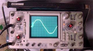
Here's an example of an X10 waveform being displayed on an oscilloscope. A special test fixture is used requiring a dual channel scope. This arrangement provides exaggerated envelope size for the X10 signal riding on the powerline 60 Hz. sine wave.
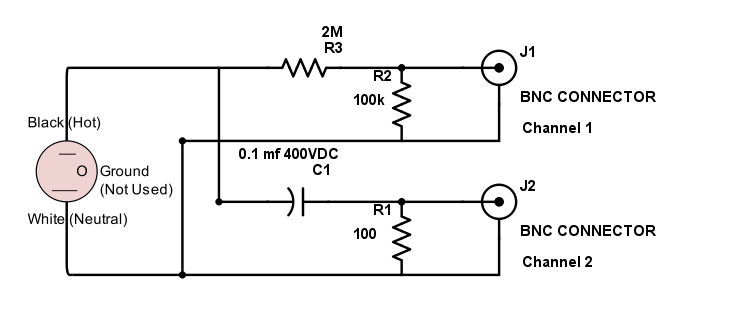
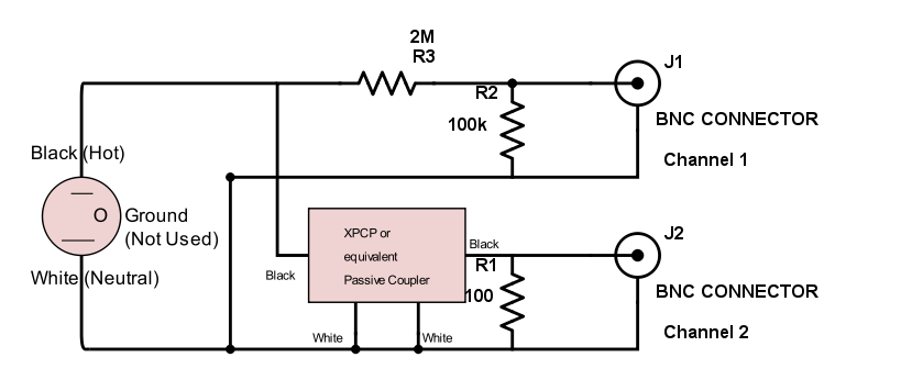
Here are the wiring diagrams of two different styles of X10 scope adapters. Be careful! These adapters can be dangerous to use if you don't know what you are doing. One side of the AC line is connected to the BNC connector shells! Make sure it's the neutral wire! Use a three-wire plug even though the ground pin is not used. Don't assume if you use a three-wire plug that your neutral wire will be correct because the outlet might be miswired!
Use of these circuits could cause serious injury or death if you don't fully understand what you are doing.
Anti-Freeze in the Heating System - How to Recharge
I used to own a house where the hydronic heating system was installed years after the house was built. It replaced the original electric heat. Because the copper pipes on the second floor run through the unheated eves there is a concern of freezing and bursting during power failures or extremely cold weather. I turn the heat down when we are not home so the concern is high. I tested the original antifreeze and it only had freeze protection down to +20 degrees F. The most trustworthy way to test the antifreeze (propylene glycol) is with a refractometer. Typically, a 50/50 mix of propylene glycol and water is used. This gives freeze protection to -30 degrees F (burst protection to -80 degrees F). When you perform maintenance, such as changing leaking vents and valves, plain water is introduced to re-pressurize the system (unless you have a stock of glycol and a pump on hand). This dilutes the glycol concentration. I purchased a refractometer for testing the glycol mixture. This is a sensitive and accurate scientific instrument and is the only way to ensure you have freeze protection short of completely draining the system, measuring the number of gallons you drained, then refilling completely with 50/50 glycol solution or half filling with 100% glycol and the rest with water.
Before replacing the glycol you should resolve any plumbing issues. Replace any valves, regulators, reliefs or seals that are leaking or oozing. When you drain the system to perform the plumbing maintenance, completely drain it and measure how much liquid was removed. When my system was totally drained I measured the volume at 20 gallons. There was no obvious service connection for introducing the new propylene glycol into the system. Some people have used the boiler drain to connect a hose and pump in the antifreeze. I heard that if you do this and shut off the valve while it is under pressure from the outside it could cause problems with the valve. Because of this, I installed a tee on the boiler side of the fill regulator along with a ball valve and hose bib. The system was recharged with water and was allowed to run for a few months to purge out any air in the lines.
For the new antifreeze I purchased 10 gallons of Cryo-Tek AG (Arctic Grade) propylene glycol. This is 100% concentrated propylene glycol. Since the system volume is 20 gallons I introduced 10 gallons of concentrate to dilute the total volume to 50% glycol. I shut off the return valve, manually opened one zone valve and pumped 5 gallons of concentrate into the new supply fitting while I drained off the equal amount of water from the return drain cock. I repeated this process closing the first zone valve and opening the second to pump the remaining 5 gallons of concentrate. Using this method I did not introduce any air into the system. I used an ordinary electric water pump with hose connections on both sides (about $40 at the hardware store). It took much longer to pump up to the second floor but it was worth the wait.
After I pumped in the 10 gallons of glycol I added water until the final pressure increased to 15 PSI. After a period of operation the solution totally mixed. I tested with the refractometer and was happy to see 47% glycol with a -27 degree F freeze point. Just for experience, I used a Cryo-Tek 35-271 test strip. It has two color pads at the end of the strip. When dipped into the solution one pad changes color to reflect the concentration. The other pad changes color to reflect the corrosion protection. My strip showed 50% glycol and the highest corrosion protection. Now I have a sample referenc
 e solution from the first day of the recharge along with the refractometer reading and the test strip.
To preserve the labor and materials investment the glycol will be tested every year. Concentrate can be added if the freeze point increases. If corrosion protection decreases, I can add Cyro-Tek 35-276 Corrosion Inhibitor. The greatest problem with glycol in heating systems is the homeowner's "set it and forget it" mentality. Decrease of the glycol pH will eventually cause many corrosion problems unless it is controlled by testing and adjusting the level of inhibitor.
Adding glycol to a heating system reduces heat transfer by 10% (for a 50% concentration), so it is more costly to run glycol not only from a maintenance perspective but also from a system efficiency (cost of fuel) perspective.
Here's the equation to determine how much 100% AG glycol to add to a running system:
(% Glycol Desired - % Glycol Present) X System Capacity in gallons = Number of gallons of concentrate to add
(100% - % Glycol Present)
Warning! Use a competent professional heating contractor for all updates or repairs on a heating system.
How to monitor the heating oil in your tank
My previous home had oil heat. Even with automatic delivery of oil, it's still possible to run out of oil. I want to receive an alarm whenever the tank falls below 1/4 full so I can call for a delivery. The oil gauge on the 275 gallon tank in the basement is a rod with an indicator disk that rises up and down inside a calibrated clear plastic cylinder that screws onto the top of the tank fitting. The cylinder can be unscrewed, exposing the rod and indicator disc. I used RTV sealant to mount a small magnet to the disk. I also used RTV to keep the disc from rotating on the shaft. The magnet needs to remain parallel to the switch so the disc can not be allowed to rotate on the shaft. The switch works best in only one magnetic N-S orientation. If you have poor sensitivity, turn either the switch or the magnet around. Then I used a 3/4 inch plastic conduit clamp to mount a reed switch at the 1/4 full level mark. When the oil level falls to 1/4, the magnet will align with the reed switch and the switch will close. The reed switch is connected to an input on the Arduino Controller. HomeSeer monitors the input and sets the state of the "Oil Low" virtual device. HomeSeer will page me over email with an "Oil Level Low Alarm."
Completely running out of oil is a pain because you usually need to have the technician purge the air out of the line to restart the burner. Anything you can do to replenish the oil before running dry is a big advantage.
I also added a second reed switch at the full mark on the oil tank gauge also connected to an input on the Arduino Controller. This tells me when the oil tank has been refilled. I did not want to rely only on the low switch turning off upon tank refilling because that switch would also turn off if the oil level dropped below 1/4 full and approached empty.
An alternate solution would be to use a taller magnet so the low switch would remain on throughout the float travel between low and empty. That would have not been possible with the low clearance between the top of the float and the top of the sight glass.
Warning! Use a competent professional heating contractor for all updates or repairs on a heating system.
[ Home | Top ]